


At Günay Heat Exchangers, we work to protect natural resources and build a sustainable future. We focus on using eco-friendly practices and maximizing energy efficiency to reduce our impact on the environment. We aim to meet future needs today and add value to society and the environment, ensuring a sustainable life for future generations


About Us
Innovative Cooling Solutions Offering High Efficiency
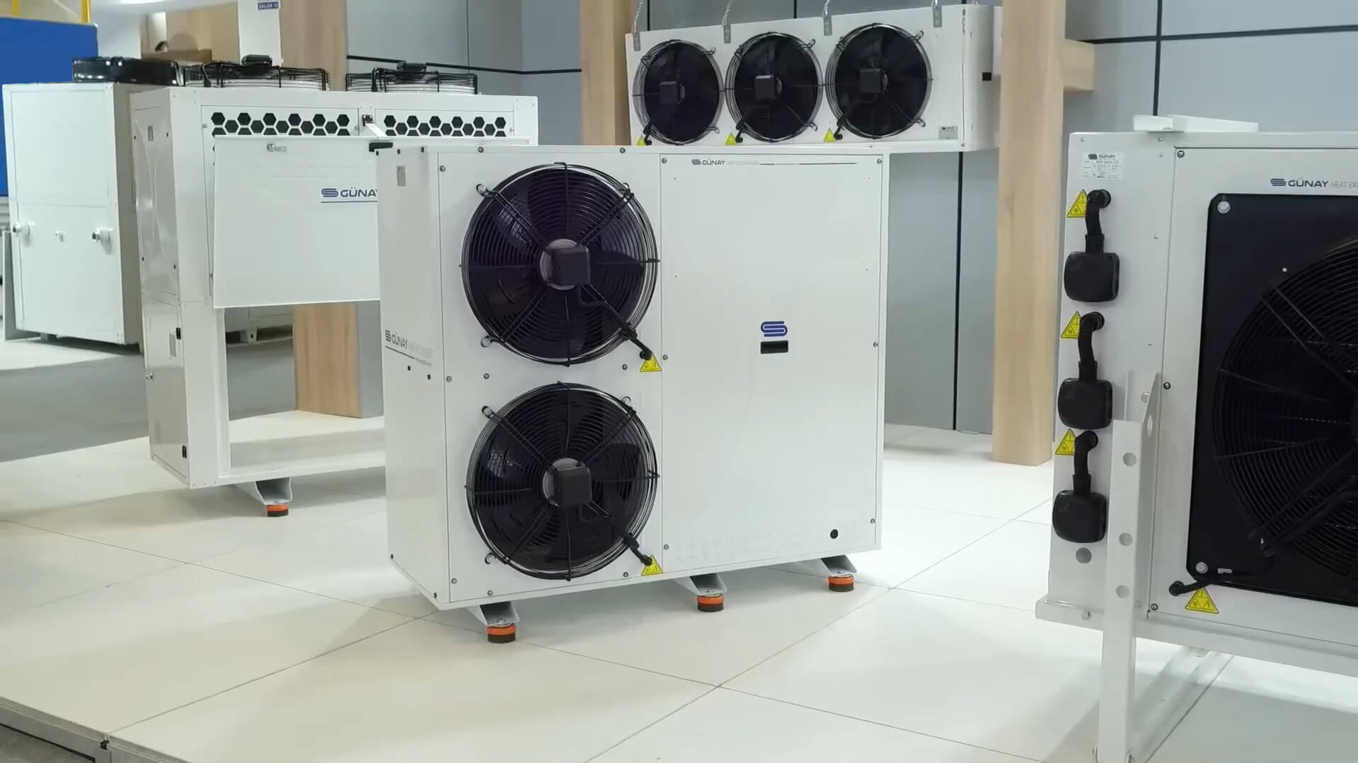
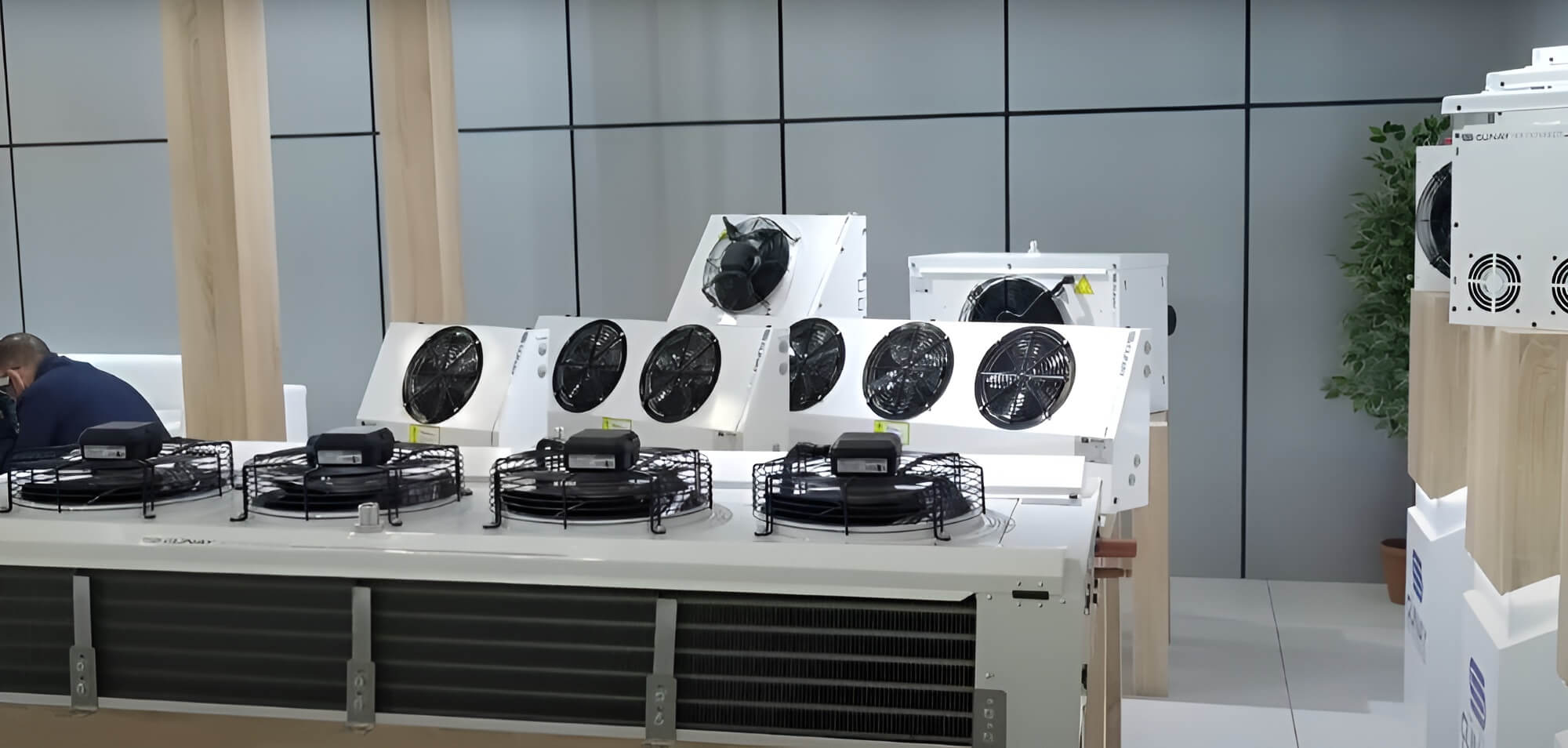
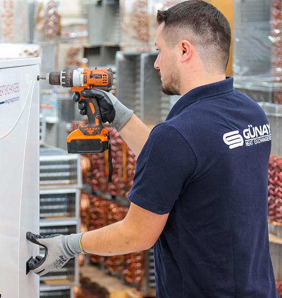
Since its establishment in 1986, our company has been offering evaporators, condensers, and heat exchangers both in mass production and as custom-made. Embracing both traditional and modern service approaches, Günay Heat Exchangers continues to evolve by constantly updating its infrastructure in line with industry innovations and customer expectations.
40
+ Years of Trust and Experience 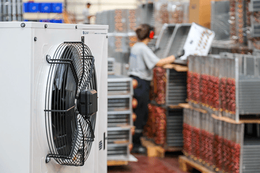
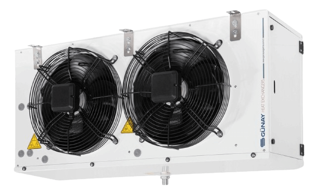
Evaporators
An evaporator is an essential component of cooling systems. Typically designed as a serpentine coil, it enables the refrigerant to evaporate and absorb heat from the surrounding environment. During this process, heat is transferred from the surroundings, thereby lowering the ambient temperature and achieving the desired cooling effect.
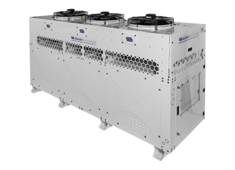
Condensers
The main function of a condenser is to condense the refrigerant gas into a liquid in the cooling cycle. During this process, the heat from the refrigerant gas is released to the surroundings, and the refrigerant condenses into a liquid form.
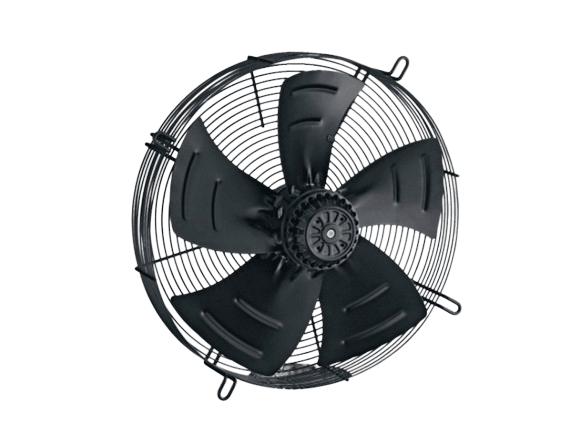
Axial Fans
Axial fans are designed to provide high airflow and play a critical role in industrial cooling solutions. These fans, which move air forward along the axis of the fan blades, are known for delivering high-volume airflow at low pressure. Thanks to these characteristics, they are an ideal solution for applications such as ventilating, cooling, or heating large areas.
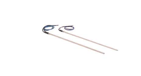
Resistances
Defrost is the process of melting frost and ice that accumulate on the surfaces of air coolers. In cold storage rooms, industrial kitchen sections, and similar areas where defrosting is needed, heaters provide suitable solutions for various heating requirements with different size and power options.
We Are With You Every Step of the Way
Safe Choice
0
+
Export to Countries
0
%
Customer Satisfaction
0
+
Employees
Contact us
Branches

Istanbul Branch
Kocatepe Mahallesi Irmak Cad. No:43-45 Beyoğlu Dolapdere/İstanbul

Factory
Yassıören Mahallesi Akpınar Sanayi Bölgesi Fırat Sokak No:6/1 Hadımköy-Arnavutköy/İstanbul
Antalya Branch
Beşkonaklılar Mahallesi Kırçiçeği Caddesi No:13E Corner City Plaza Kepez/Antalya

Izmir Branch
Barbaros Burak Reis Caddesi No:112 D:A, 35090 Bornova/İzmir

Günay Academy
Education Workshop


For More
Follow the Agenda
Blog
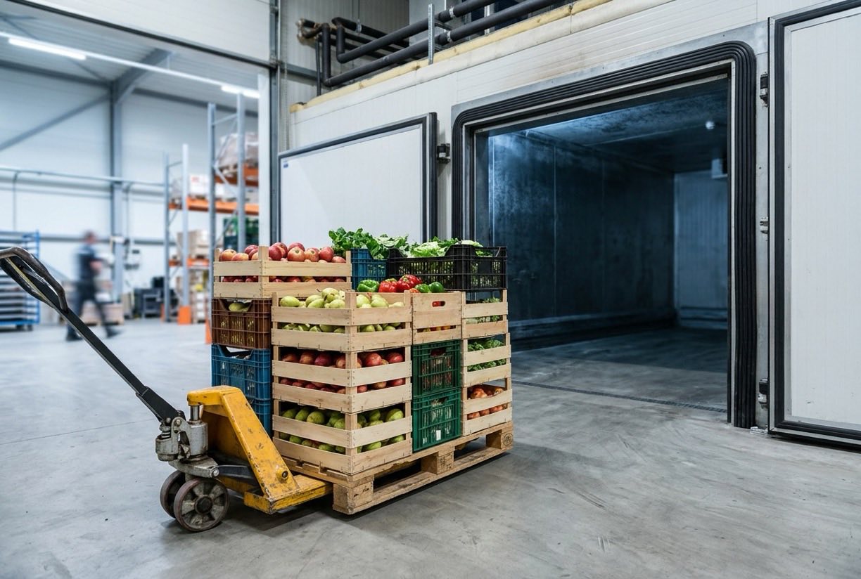
Products entering a cold room arrive at a temperature higher than the room or target temperature. Cooling them is a major part of the room cooling load and should be evaluated as a separate item in the capacity calculation. If this item is ignored, the evaporator is undersized and the room cannot reach its target during peak intake hours. This article explains how the product entry heat is calculated, which data are needed, and how the calculation affects the evaporator selection. Table Of Contents Why Is The Product Entry Heat Calculated Separately? Which Data Are Needed? How Is The Product Entry Heat Calculated? What Is The Effect Of Packaging And Transport Containers? How Does The Calculation Affect Evaporator Selection? Frequently Asked Questions Why Is The Product Entry Heat Calculated Separately? The product entry heat comes from a different source than the heat entering through the walls and the door. Wall and door losses are continuous, while the product entry load is concentrated in specific hours. For this reason the two items should be calculated separately and then added together. The entry load alone can make up a large part of the evaporator capacity. This effect is especially clear when large daily batches of product arrive. Product entry heat is the amount of heat that must be removed to cool a product brought into the room, and it is assessed separately from heat leakage through the door and insulation. This load can reach very high values in a short time, depending on when and how much product enters. It therefore needs a separate calculation. Leakage and transmission loads usually follow a continuous and predictable pattern. Product entry, on the other hand, is an intermittent, intense and variable load. Showing these two loads as a single average hides the moment when the system is most stressed. The product entry load directly affects whether the evaporator capacity is sufficient. During a period of heavy entry, the evaporator must work above its design load. This can delay the room from reaching its target temperature and can affect product quality. Another reason for calculating the entry heat separately is the cooling requirement, which varies with the type of product. Fresh produce, frozen goods and packaged products each enter the room with a different heat content. This difference requires the calculation to be made by product type. The calculation should be made together with the operating plan of the facility. Entry times, dispatch arrangements and production capacity determine how the product entry is spread over time. A calculation made without knowing this distribution can lead to a wrong capacity decision. Product entry load is also a significant part of the running cost. Irregular entry makes the system run at high power for short periods. This kind of operation raises both energy consumption and wear on the equipment. Which Data Are Needed? The calculation needs the daily entry quantity, the entry temperature of the product, the target storage temperature, and the specific heat of the product. For frozen products, the latent heat released during freezing must also be included. Daily quantity: The total product entering during the day, in kilograms. Entry temperature: The temperature of the product at the moment it enters the room. Target temperature: The temperature at which the product will be stored. The most important data for the calculation is the quantity of product entering the room each day. This quantity should be set according to the product type and the production plan of the facility. A realistic quantity rather than an estimate is essential for an accurate calculation. The entry temperature of the product, the target operating temperature and the difference between these two values form the basis of the calculation. The temperature difference shows how much heat the product carries. An estimate made without measuring the entry temperature may be the weakest link in the calculation. The specific heat of the product, meaning the energy needed to change the temperature of a unit mass by one degree, varies with the product type. Products with a high water content and dry products bring different heat loads at the same temperature difference. This value should be taken from manufacturer or reliable source data. Whether the product enters above or below its freezing temperature affects the calculation. The latent heat released during freezing should be assessed separately from the normal cooling load. This distinction is especially important for frozen products. The mass of the packaging, and auxiliary materials such as pallets and crates, should also be included. These materials enter the room with the product and carry their own heat load. Neglecting the packaging load leaves a missing item in the calculation. Another data item needed is the time within which the product must be cooled. This time is determined by product quality and by the dispatch arrangement of the facility. As the cooling time gets shorter, the power the product requires also rises. How Is The Product Entry Heat Calculated? The heat to be removed is basically found by multiplying the mass, the specific heat, and the temperature difference: Q = m × c × ΔT. Here m is the product mass, c is the specific heat of the product, and ΔT is the difference between the entry temperature and the target temperature. For products that pass from above freezing to frozen, the latent heat of the phase change is added separately. The result should be distributed over the busiest hours of the day to find the highest instantaneous load. An average value may not be sufficient during the intake hours. The sensible heat calculation is made by multiplying the mass of the product, its specific heat and the temperature difference. The value obtained gives the total heat that must be removed within a given time. Dividing that time gives the average hourly load. When the calculation is made, the heat load of the packaging and transport container must be added, not only that of the product itself. Although the mass of the packaging is usually smaller than that of the product, in some cases it can make up a large part of the total load. For this reason each item should be calculated separately. Respiration heat arises in living products such as fresh fruit and vegetables. These products continue their vital activity even in a cold room, and during this they produce heat. The respiration load varies with the type and temperature of the product and should be added as a separate item. For frozen products, the latent heat forms a separate part of the temperature drop. The energy needed for the water in the product to freeze at freezing temperature should be considered in addition to the normal cooling calculation. This part can significantly increase the calculation. The result should include a peak load as well as the daily total load. The peak load is the value that the evaporator must meet at the time of heaviest entry. The evaporator should be selected so that it can handle this peak. The results of the calculation should be supported by a safety margin. The margin is used to cover measurement uncertainties, unexpected entry fluctuations and changes in product range. Its size should be set according to the flexibility of the facility. What Is The Effect Of Packaging And Transport Containers? Packaging, pallets, and transport containers that enter the room together with the product also carry heat. A metal crate, a plastic crate, and a cardboard package have different heat capacities. These materials must also be cooled along with the product and should be included in the calculation. The mass of the packaging may look small compared with the product, but metal pallets and crates can create a significant heat load. Packaging is part of the heat load as well as a means of protecting the product. When the packaging material enters the room, it must bring its own temperature down to the cooling temperature. For this reason the mass and heat capacity of the packaging should be taken into account. Crates, boxes and pallets are often brought into the room again and again with the product. This equipment must be cooled again each time it enters. The number and mass of the equipment used affect the total load noticeably. The thermal conductivity of the packaging also matters. Insulated packaging reduces the heat the product takes from the outside and lowers the cooling load. However, leaving insulated packaging in the room for a long time can create a different effect on the heat balance over time. How warm the transport container is before entering the room also affects the calculation. A crate that has been held outside brings more heat in when it enters. For this reason the holding time and condition of the container before entry should be checked. The choice of packaging and transport containers should be made together with the operating plan. Assessing packaging in terms of lightness, ease of transport and heat load can bring significant savings in the long run. This decision should be taken by product and logistics teams working together. Cleanliness and dryness of reusable transport equipment is also part of the calculation. A wet or dirty crate can bring extra moisture and load into the room. Equipment entering clean and dry protects both the load and the hygiene. How Does The Calculation Affect Evaporator Selection? The product entry load is added to the total cooling load and enters the capacity selection of the evaporator. The selected capacity should be evaluated so that it covers the load during the busiest intake hour. If this load has been calculated on average, the room may occasionally rise above target. The result should also be compared with the standard conditions of the evaporator catalogue. The Günay Soğutma technical team can support reflecting this calculation in the evaporator selection, based on your project data. The result of the product entry heat calculation is one of the basic inputs that determine the capacity of the evaporator. The peak load from the calculation is taken as the value the evaporator must meet in selection. If the evaporator falls below this value, the cooling time becomes longer and the room temperature may stay above target. Evaporator selection must include the leakage and transmission loads as well as the entry load. The total load is determined by the sum of these three sources. If one item of the calculation is missing, the selected evaporator cannot meet the real load. The difference between the peak load and the average load also determines the capacity flexibility of the evaporator. If the difference is large, a variable-speed system or several evaporators may be more suitable. This decision should be made according to how the load is distributed over time. The fit between the design temperature difference of the evaporator and the calculation is also important. The evaporator should be selected to work at the target temperature of the room and under the required load condition. The conditions under which the catalogue values were obtained should be known for the selection to be accurate. In conclusion, the correct calculation of product entry heat is the key to an evaporator that works both adequately and efficiently. Where the calculation is not made or is incomplete, the system has problems in both capacity and energy. The calculation should therefore be treated as the first step of the selection. After selection, comparing the calculation with real operating data improves later decisions. If actual entry quantities and temperatures are recorded, the estimate will be more accurate in the next project. This record forms a valuable data source for the facility. Frequently Asked Questions What share of the total load does the product entry heat make up? This share depends on the product quantity, the entry temperature, and the insulation condition. Giving a fixed share would be misleading; it must be calculated for each project. Is pre-cooling calculated separately? If products arrive already cooled to a lower temperature from a pre-cooling room, a separate calculation is needed for that room. The load of the main room is calculated from the entry temperature of the incoming product. What happens if the daily entry quantity changes? The average load changes, and on busy days the room can rise above target. For this reason the design should be based on the quantity of the busiest day. How should the product temperature be measured? Product temperature should be measured with a sensor placed inside the product or with a calibrated thermometer. The surface temperature may not reflect the internal temperature. The measurement should be made just before entry and recorded. ? What safety margin is used in the calculation? The safety margin is set according to the uncertainty of the data, the entry fluctuations and future capacity needs of the facility. Its size should match the risk level of the decision. The margin should be shown clearly in the calculation and its reason written down.
Read More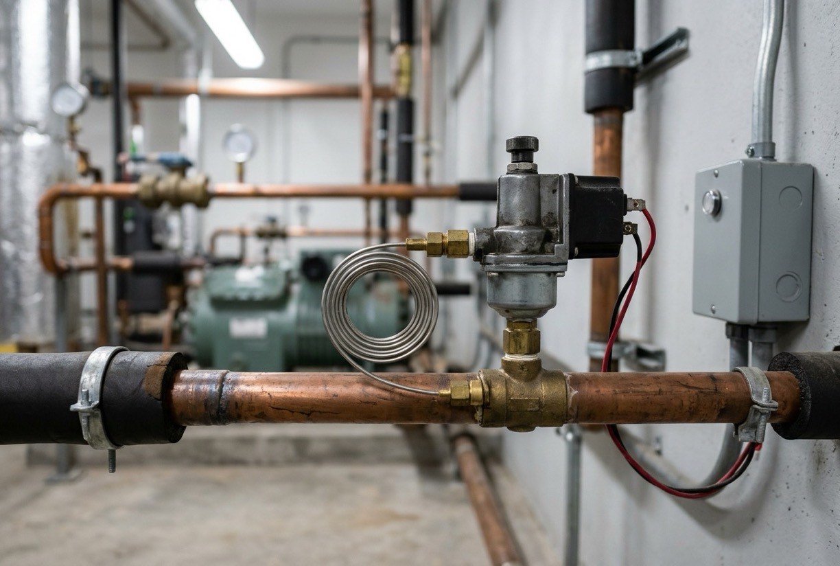
When the condensing pressure rises above a set value, the compressor and other parts of the system can be damaged. In this case the high-pressure switch is the safety element that protects the system by stopping the compressor. However, if the switch is not set according to the normal operating range of the system, it either trips too often or reacts too late in a real danger. This article explains why high-pressure protection is needed, the causes related to the condenser, and the principles of setting. Table Of Contents Why Is High-Pressure Protection Needed? How Does A High-Pressure Switch Work? Why Does The Condensing Pressure Rise Because Of The Condenser? How Is The Setting Value Determined? How Are Repeated Trips Evaluated? Frequently Asked Questions Why Is High-Pressure Protection Needed? When the condensing pressure rises excessively, the compressor motor works under heavy load, seals are stressed, and the compressor life is shortened. The purpose of high-pressure protection is to stop the compressor safely before this condition develops. The protection should be selected to act below the design pressure of the system. Otherwise it serves no purpose. High-pressure protection is the last safety layer that prevents the compressor from running with a load beyond its design limits. The control system and fan settings manage the pressure under normal conditions; the protection acts at the moment that management fails. Its purpose is therefore to end a dangerous condition, not to keep the unit running. High pressure affects not only the compressor but every component of the system. Pipe joints, brazed seams, service valves and oil circulation are all stressed at high pressure. Over time this stress raises the risk of leaks and lasting damage. As pressure rises, the compressor discharge temperature rises too. A high discharge temperature can break down the oil and form carbon deposits on the internal parts of the compressor. For this reason high pressure and high temperature should be assessed together. The presence of a protective device must not be used to hide design faults in the system. If the protection trips often, this is a warning and the root cause should be sought. The protection also gives useful information as a diagnostic aid. High-pressure protection matters for the safety of operating staff as well. During maintenance a wrong action can cause a sudden rise in pressure. The protection helps safeguard the machine and its surroundings in such events. The correct choice of protection depends on the pressure limits set by the compressor manufacturer. Each compressor and each refrigerant has its own limit. The protection should be selected with all these limits in mind. How Does A High-Pressure Switch Work? The high-pressure switch is connected to the compressor discharge line and senses the pressure through a capillary tube. When the pressure exceeds the set value, its contacts open and disconnect the compressor contactor. It closes again after a defined differential, and the reset can be automatic or manual. A high-pressure switch senses the pressure through a diaphragm or bellows and opens the electrical circuit when the set value is reached. Because this mechanical design works without an external energy source, it is considered reliable. The pressure at which the switch responds is a value that can be adjusted on the device. The switch takes its pressure reading from the system through a capillary tube. The tightness and freedom from damage of the capillary tube are essential for correct operation. If the capillary tube is broken or kinked, the switch cannot see the true pressure and loses its protective function. The contacts of the switch open at the set pressure and disconnect the contactor of the compressor. The contacts must be rated to carry the compressor current directly. Wear of the contacts can cause false tripping or welded contacts. Some switches close again by themselves when the pressure falls, while others need a manual reset. This difference determines how the protection behaves and who is responsible for it. Where automatic reset is used, precautions must be taken against restarting before the cause has been removed. The switch's differential sets the gap between its cut-out and cut-in pressures. If this gap is too narrow the switch cycles too often; if it is too wide, restarting is delayed for a long time after the pressure has fallen. The differential should be chosen to suit the design of the system. The physical position of the switch also affects its response. If the capillary tube runs through a very long or hot route, the pressure read by the switch may not reflect the real value. The installation should cover the route of the capillary tube and the position of the switch. Why Does The Condensing Pressure Rise Because Of The Condenser? The most common cause of high condensing pressure is that the condenser cannot reject heat sufficiently. Dirty fins, a blocked air path, a fan that is not running, a poor layout, and recirculation of warm discharge air can all cause this effect. Dirty fins: Reduce heat transfer. Fan failure: Airflow falls. Air recirculation: The condenser takes in its own discharge air. An excess refrigerant charge in the system can also raise the condensing pressure. High condensing pressure caused by the condenser is the most common situation. The heat rejection capacity of the condenser depends on the cleanliness of its surface, the operation of its fans and the path of the airflow. If any one of these three is impaired, the pressure can rise quickly. A dirty condenser surface reduces heat exchange because of dust, fluff and oil that collect between the fin spacings. This causes the pressure to rise slowly and eventually reach the protection threshold. The rate at which this build-up occurs should be considered when planning cleaning. A fan that is not running can stop the airflow across the condenser completely. When the fan motor, the contactor or the control signal fails, the pressure can rise within a very short time. Monitoring the running state of the fan helps to notice such a failure early. The location of the condenser is also an important factor. If the condenser is placed near a hot air outlet or in an enclosed area, the intake air temperature rises and the condensing pressure increases. The layout should allow air to enter and leave freely. Non-condensable gases such as air, and excess refrigerant charge, both raise the pressure. Excess charge fills part of the condenser with liquid and reduces the effective surface. Non-condensables raise the pressure directly. Charge and vacuum control should therefore be among the first steps in any system with a pressure problem. When the ambient temperature is high, the capacity of the condenser is already limited. In such periods the protection can be an early warning that the system is approaching its design limit. Seasonal changes must always be considered when assessing the protection setting. How Is The Setting Value Determined? The setting value is determined by considering together the pressure-temperature table of the refrigerant in use, the maximum operating pressure of the compressor, and the normal condensing pressure of the system. The setting should be above the normal operating pressure but at the limit that protects the compressor. After setting, the system should be monitored at the highest ambient temperature, and the agreement between the switch and the real value should be confirmed. The setting value should be fixed at a point above the design pressure of the system but below the safe limit of the compressor. This range is found by assessing the manufacturer's data together with the pressure-temperature relationship of the refrigerant in use. An estimated value does not make the protection reliable. When setting the value, the highest pressure reached under normal operating conditions must be known. The highest outside temperature in summer determines the highest pressure the condenser will reach. The setting should be above this high pressure but below the limit. If the setting is chosen too low, the protection trips during normal operation. This disrupts operation and places an unnecessary load on the protective device. A setting that is too low means the protection will act without a serious event occurring. If the setting is chosen too high, the protection loses its function. If the pressure reaches dangerous levels without the protection tripping, the compressor may continue to run under hazardous conditions. The setting should therefore be placed between the requirements of safety and of operation. After the setting is made, it should be verified by measurement under both normal and peak conditions. The measurements show whether the setting covers the real operating range. The result of the verification should be recorded. A change of setting should not be made once and then forgotten. A new refrigerant, a change of condenser or a change of layout requires the setting to be reconsidered. Setting records help to track all of these changes. How Are Repeated Trips Evaluated? If the switch trips often, the cause should be investigated first. Raising the setting hides the problem and can put the compressor at risk. Condenser cleaning, fan checks, and the openness of the air path are the first points to check. The Günay Soğutma technical team can provide project-based support on condenser selection and control settings. Repeated tripping shows that the protection is signalling a problem. Simply resetting the protection to pass these trips does not solve the problem itself. The time, the outside temperature at that moment and the operating state should be recorded for each trip. The timing of the trips can give hints about the source of the problem. Repeated trips during the hottest hours of the day can point to insufficient condenser capacity. A trip at night, on the other hand, may be due to a different cause, such as an imbalance of oil or refrigerant. The pressure value at the moment of tripping shows whether the protection is acting at the correct threshold. If a trip occurs while the pressure is below the threshold, a fault in the switch or the capillary tube should be considered. This distinction prevents unnecessary compressor replacements. With repeated trips, the condenser and the fan are the first things to check. Next, the charge of the system, the presence of non-condensable gas and the layout should be assessed. This order reduces the loss of time. As the frequency of trips increases, the mechanical load on the compressor also increases. A system that keeps cycling on and off causes extra wear on the contactor and the compressor motor. For this reason repeated trips should be handed to a specialist for timely examination. Repeated trips should also be reflected in the maintenance plan. A record of these events can be used to schedule later maintenance. Interventions made without a record lead to the same problem recurring. Frequently Asked Questions Does a high-pressure switch really protect the compressor? When set correctly, it protects the compressor from excessive pressure load. However, the switch does not remove the cause; it must work together with the condenser and system control. Is bypassing the switch a solution? No. A bypass leaves the compressor unprotected and can cause serious damage. The cause must be found and removed. Can the high-pressure switch trip in winter? In winter the problem is usually low pressure. However, if the condenser fan control has been set incorrectly, the high-pressure switch can also trip in winter. Which reset type should the high-pressure switch have? The reset type should be chosen according to how the system is monitored and how it is attended. Automatic reset can create a dangerous risk of restarting in facilities that are not continuously monitored. Manual reset prevents restarting before the fault has been examined, but the intervention must be possible quickly. ? How should the switch and the condenser fan relate to each other? The switch is the last safety element that acts when the condenser fan is not enough. The fan control tries to reduce the pressure in advance. The switch stops the compressor when that control has failed. Together they should form a layer in which each completes the other.
Read More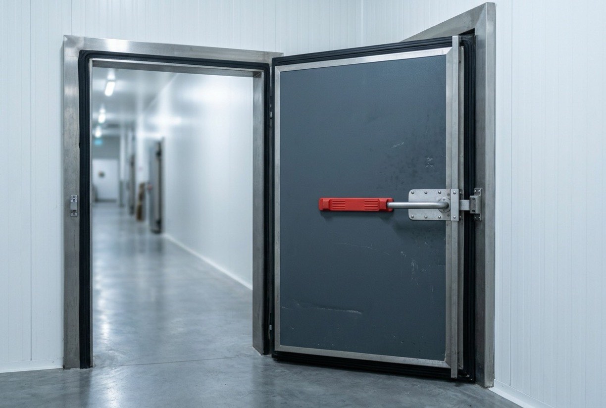
The cold room door is the most frequently used passage between the inside and the outside, and most of the temperature loss happens there. A wrong door type, an undersized opening, or a damaged gasket can cause energy loss, frosting, and safety problems. This article explains how to choose the door type, how the door size relates to traffic, and why the safety hardware is critical. Table Of Contents How Is The Door Type Selected? What Is The Relation Between Door Size And Traffic? Why Are The Gasket And Closing Mechanism Important? How Is Frosting Prevented? How Are Safety And Inside Release Ensured? Frequently Asked Questions How Is The Door Type Selected? The common door types are hinged doors and sliding doors. Hinged doors are simpler and more common, but they need space in front when they open. Sliding doors save floor space, but they need the track and gasket system to be installed more carefully. The choice should consider the layout of the room, the frequency of use, and the passage of handling equipment. Door type selection starts with the purpose of the room. How often the door will be opened, which loads will pass through it, and how much free space exists around it are the first determinants of the most suitable type. The same type that works well in one warehouse may cause problems in another production area. Hinged doors need enough free space on both the inside and the outside when the leaf opens. The direction of opening, the corridor width, and the passage of pallet trucks should be considered together. If the opening direction is chosen wrongly, the door is left open for long periods, causing energy loss and disruption to the workflow. Sliding doors offer an advantage, particularly for facilities working in a limited space. However, the track system must be installed at the correct slope and on a sound floor. Dirt and ice that build up on the track can prevent the door from moving freely, so track maintenance should be planned with an easy-access design. The material of the door leaf and its insulation thickness also affect the choice. The leaf must provide the same performance as the insulation of the room wall; otherwise the door becomes the weakest link in the room. The surface material should suit cleaning and hygiene requirements. Maintenance access should also be considered when selecting the door type. Easy access to hinges, tracks and locks shortens the response time in the event of a fault. A door that is difficult to reach can turn a small problem into a major interruption. What Is The Relation Between Door Size And Traffic? The door size should be defined according to the comfortable passage of handling equipment and products. An oversized door can increase the time it stays open and the entry of warm air. A small door slows down the workflow and can cause the door to be opened more often. Door traffic directly affects the load on the evaporator. For this reason, the door choice should be evaluated together with the evaporator and insulation decisions. Door size is related not only to the comfort of passage but also to the heat load of the room. When a large door stays open, the amount of warm and humid air entering from outside increases. The door should therefore be chosen at the smallest size the need requires, without compromising working safety. The passage dimensions of the products and handling equipment set the minimum door size. Pallet trucks, forklifts and trolleys need clearance when passing through the door. A door chosen without calculating this clearance may later need to be replaced. The intensity of door traffic is related not only to size but also to the speed of opening. Doors that open and close quickly shorten the time they stay open and reduce warm air entry. The door type and closing speed should therefore be evaluated together with the traffic intensity. The daily working pattern of the facility also shapes door traffic. Shift changes, dispatch times and production peaks determine the periods when the door is opened most. Knowing these periods shows where and when additional measures should be applied. Door traffic directly affects the load on the evaporator, so the door choice should be considered together with the evaporator and insulation decisions. The extra load from a frequently opened door can leave the evaporator capacity insufficient. This effect should be taken into account at the design stage. Door size should also consider future capacity increases. If product variety or production volume is set to grow, a door that seems adequate today may become a bottleneck in the near future. A flexible plan reduces this risk. Why Are The Gasket And Closing Mechanism Important? The door gasket compresses when the door closes and stops the air passage. If the gasket wears, deforms, or becomes dirty, a leak forms, and this leak returns as frosting and energy loss. The closing mechanism should be adjusted to press the gasket with adequate force. The gasket replacement frequency and inspection plan should be part of the maintenance programme. The door gasket is the most important element that cuts off air exchange between the cold room and the outside. When the gasket is intact, the door forms an airtight surface when closed. When the gasket is damaged, the warm air entering the room causes both energy loss and condensation on the surfaces. The gasket material should be chosen for its resistance to temperature and its flexibility. A gasket that hardens or cracks in cold conditions loses its effect within a short time. When selecting the material, the minimum temperature of the room and resistance to cleaning chemicals should also be considered. The closing mechanism must be adjusted so that the gasket is pressed with adequate force. When the hinges, the lock and the handle work together, the door should apply an even pressure along the frame. If there is not enough pressure at one corner, a leak forms there, and that is often the last place where it is noticed. Checking the gasket and the mechanism should be part of a regular maintenance plan. During inspection, signs of tearing, deformation and dirt on the gasket should be examined by eye, and the seal should be tested by feeling it after the door closes. This check ensures that problems are noticed before they grow. The gasket replacement frequency and inspection plan should be part of the maintenance programme. Doors that are opened frequently need a shorter replacement interval, and the date of each replacement should be recorded. Such records show how long a gasket lasts and under which conditions it wears out earlier. Scratches on the door surface and on the gasket seating face can also cause leaks. Hard tools used during cleaning may damage the gasket groove. Cleaning instructions should be prepared so that they protect these surfaces. How Is Frosting Prevented? Frosting around the door forms when warm, humid air condenses on the door surface. As a countermeasure, heating elements can be used around the door, and thermal bridges between the door and the frame can be cut. Controlled operation of the heater prevents unnecessary energy use. Door frame heater: Limits condensation and frosting. Thermal bridge: No break in the insulation should be created between the door and the frame. Control: The heater should be set to operate only when needed. Frosting around the door forms when warm, humid air condenses and freezes on the cold door surface. It prevents the door from opening smoothly and can leave a permanent layer of ice around it. Preventing frost matters both for operating safety and for energy efficiency. Heating elements keep the surface temperature of the door frame above the dew point and so prevent condensation. The heater's power should be chosen according to the room temperature and the moisture load. An oversized heater wastes energy and can create an unwanted heat source around the door. Thermal bridges between the door and the frame must be cut. Cold bridges formed through metal fixings and frame profiles cause the surface to cool quickly. Keeping the insulation continuous reduces both frosting and energy loss. Controlled operation of the heater prevents unnecessary energy use. Rather than being left on continuously, the heater should be run according to the surface temperature and the humidity condition. A timed or sensor-based control is the most practical way to achieve this balance. Frost is not only a comfort issue. It also prevents the door from closing properly and puts strain on the door mechanism. Strained hinge and lock parts can break over time. When ice build-up is seen, treating only the surface is not enough. How Are Safety And Inside Release Ensured? For a person locked inside a cold room, a handle that can be opened from the inside is vital. For this reason, cold room doors should have an inside release mechanism and an alarm or illuminated warning. An arrangement that allows the person inside to communicate with the outside when the door is locked should also be considered. Safety hardware should be selected taking into account local regulations and occupational safety requirements. The Günay Soğutma technical team can support the evaluation of door and evaporator selection together, based on your project data. When a worker is locked inside a cold room, being able to get out is vital. The handle that opens from the inside must therefore be an indispensable part of the room design. The handle should be designed so that it can be easily noticed and operated even with gloves on. Besides the inside release mechanism, the room should have an alarm or an illuminated warning. The alarm should be able to transmit to a place outside the room, and its sound should be noticeable at the noise level of the room. Regular testing of the warning system ensures it works in an emergency. An arrangement that allows the person inside to communicate with the outside when the door is locked should also be considered. A simple intercom or call button can save a life in a critical moment. This arrangement should be clearly explained in the room's operating instructions. Emergency drills help staff remember the procedure. A person who has only read the instructions may hesitate in a real emergency, while a person who has practised the release will act faster. Keeping training records also documents that the arrangement is actually known to the staff. Frequently Asked Questions Should a hinged or sliding door be preferred? The space, the frequency of use, and the handling equipment are the deciding factors. A hinged door is common and simple; a sliding door gives an advantage in a limited space. Is additional heating needed for a cold room door? In environments with a freezing risk, especially in rooms operating below zero, heating around the door may be needed. In rooms at positive temperature the need can be lower. How often should the door gasket be checked? It should be checked at regular intervals according to the intensity of use. For doors that are opened frequently, the checking frequency should be increased. Which way should the door swing? The opening direction determines which area the door occupies during use and which equipment can pass the corridor. If the wrong direction is chosen, the door cannot open fully or the handling equipment gets stuck. The opening direction should therefore be fixed together with the layout plan. How should the door lock be selected? The lock should be operable from the inside and designed according to the need for access from outside. Options such as key, card or code should be decided by balancing security against ease of use. The ability of the lock to work in the cold must also be checked. How should the door insulation match the wall insulation? The door leaf should provide an insulation performance similar to the wall insulation of the room. The connection between the leaf and the wall should be designed so that it does not create a thermal bridge. If this match is not achieved, the door becomes the weakest link in the room.
Read More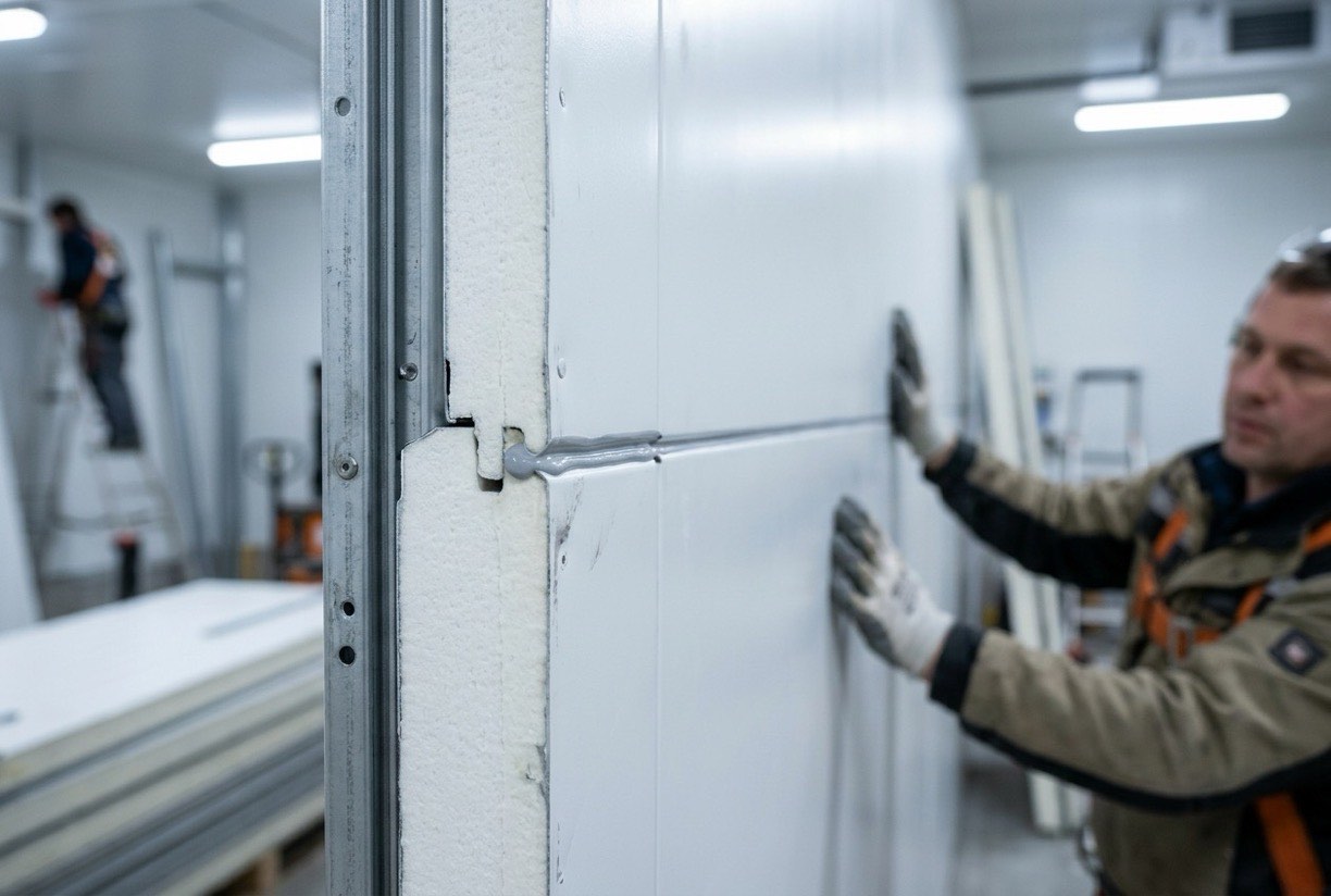
The walls, ceiling, and floor of a cold room continuously transfer heat from the outside in. This heat leakage directly affects the energy used by the evaporator and the compressor. The insulation thickness of the panels is one of the most important design decisions that limit this leakage. This article explains why insulation thickness is critical, how heat leakage is calculated, and what to consider when selecting panels. Table Of Contents Why Is Insulation A Critical Decision? How Is Heat Leakage Calculated? Which Parameters Define The Panel Thickness? Which Insulation Materials Exist? Why Are Joints And Corner Details Important? Frequently Asked Questions Why Is Insulation A Critical Decision? Insulation defines a large part of the cooling load of a cold room. Insufficient insulation leads to continuous operation of the system and more frosting on the evaporator. Insulation that is thicker than necessary can increase the investment cost without need. The right thickness should be defined according to the purpose of the room, its temperature level, and the outdoor conditions. Cold room insulation is a basic structural element that determines both the running cost and the temperature stability of the room. When the insulation is weak, the refrigeration system works continuously against heat coming in from outside and spends much of its capacity on that loss. The panel thickness is therefore a decision that affects the whole system, even though it may look like a simple cost item at first sight. The choice of thickness depends not only on the thermal conductivity of the insulation material but also on the operating temperature of the room, the external climate and the purpose of the room. The level of insulation needed for frozen products is higher than that needed for a room held at positive temperature. This difference shows that the decision should not be reduced to a single value. Inadequate insulation leads not only to energy loss but also to condensation and frosting on the surfaces. When the temperature on a wall or ceiling surface drops below the dew point, moisture collects on the surface and gradually damages the building material. The insulation decision should therefore also be assessed for hygiene and the health of the structure. The insulation thickness should be considered together with the capacity calculation of the system. A thicker insulation reduces heat leakage, so the evaporator and the compressor can run with a smaller load. This effect can also be a source of saving when the equipment is selected. Another factor influencing the insulation decision is the layout of the room. Rooms with a shared wall, rooms that open onto the external facade and rooms under a roof experience different heat loads. Assessing each surface separately reduces the risk of unnecessary thickness or insufficient insulation. How Is Heat Leakage Calculated? Heat leakage depends on the wall and ceiling surface areas, and on the thermal conductivity and thickness of the material. As the difference between the outside and inside temperatures grows, the leakage increases. The calculation should also include additional losses such as doors and penetrations. The result should be evaluated together with the capacity selection of the evaporator. The insulation decision directly affects the capacity decision. The heat leakage calculation is made by adding up the heat passing through every surface of the room. For each surface, the thickness of the insulation material, its thermal conductivity and the surface area are assessed together with the difference between the outside and inside temperatures. This approach also shows which surface makes the insulation decision most critical. When the calculation is made, the outside temperature value should be chosen to represent the worst condition of the year. A calculation based on an average summer or winter value may fall short under peak conditions. For this reason the design outside temperature should include the extreme values of the climate data. In addition to heat leakage, the load from product entry and from door openings should also be taken into account. These are loads that may seem independent of the insulation but still influence its selection. Keeping the insulation low and leaving out the load of a frequently opened door causes an error in capacity. The result of the calculation should not be seen as a single figure. Comparisons made for different thicknesses show the return of each increase in thickness. Such a comparison can also show the point beyond which a further increase in thickness no longer brings any additional gain. The accuracy of the calculation depends on the realism of the material values used. Manufacturer data should be the basis, but the losses at joints created during installation should also be considered. The gap between the theoretical value and the real value on site can come from these losses. Which Parameters Define The Panel Thickness? The selection considers the room temperature, the outdoor temperature, the thermal properties of the panel material, and the surface areas of the room together. Rooms in sunny or humid locations may also need a different approach. Room temperature: The lower it is, the thicker the insulation may need to be. Outdoor environment: Hot and sun-exposed surfaces add more load. Surface area: Large wall and ceiling losses become significant. The panel thickness is determined first of all by the operating temperature of the room. A room operating at a low temperature requires thicker insulation to cope with the large temperature difference from the outside. As the room temperature falls, the thermal effect of this difference increases and the role of the insulation becomes more pronounced. External climate conditions also affect the thickness. In regions where the outside temperature rises very high in summer, the insulation's role in limiting heat gain is more important. In regions where the outside temperature drops in winter, the effect of the insulation on heat loss should be assessed differently. The size and shape of the room also influence the choice. In small rooms where the ratio of surface area to volume is high, most of the heat leakage comes through the surfaces. In large and compact rooms the surface area is relatively small. This difference means that the geometry of the room should also be taken into account in the thickness decision. The product type and the temperature tolerance required by the product are also parameters. When a sensitive product must be kept within a narrow temperature range, the ability of the insulation to limit temperature fluctuation becomes important. This takes the choice of thickness beyond the energy calculation alone. The mechanical properties of the panel should also be considered when choosing the thickness. Thicker panels may need a different installation plan because of weight and handling requirements. For this reason the thickness should also be assessed from the structural and installation point of view. Finally, regulations and facility requirements may impose a minimum insulation level. These requirements set a boundary below the technical calculation. When choosing, both the technical calculation and the legal requirements should be checked together. Which Insulation Materials Exist? For cold room panels, sandwich panels with a polyurethane or polystyrene foam core are commonly used. Each material differs in thermal conductivity, fire behaviour, and cost. The choice should consider the purpose of use and legal requirements. Different materials at the same thickness can give different insulation performance. For this reason, thickness alone should not be the comparison criterion. Insulation materials differ in thermal conductivity, moisture behaviour, fire class and cost. Polyurethane, polystyrene and mineral wool are among the most frequently used options in cold room applications. Each has its strengths and weaknesses, and the choice should be made according to the conditions of use. Polyurethane foam can provide the same insulating effect with a thinner panel thanks to its low thermal conductivity. This property helps make better use of the floor area of the room. However, the fire behaviour and class of the material must match the requirements of the facility. Polystyrene materials provide acceptable insulation at a lower cost. However, they may require a thicker panel and need careful installation to deal with moisture. The surface coating and the joint details significantly affect the performance of this material. Mineral wool is preferred in facilities where fire safety is particularly important, because of its resistance to fire. However, because of its tendency to absorb moisture, it requires a suitable barrier on the outer surface. For this reason moisture management should be planned when mineral wool is selected. Material selection should be assessed together with the surface coating of the panel. The surface material affects the performance of the insulation in terms of ease of cleaning, mechanical strength and vapour permeability. For this reason the panel should be chosen as a whole, together with its coating, not only on the basis of the insulation inside it. When a material change is made, the weight and the installation capacity of the existing structure should be checked. A material of different density can create an additional load on the supporting structure. Such an assessment ensures that the choice of material matches the reality of the facility. Why Are Joints And Corner Details Important? Panel joints, corners, and the door surround are the weak points of insulation. If gaps or thermal bridges form at these points, the panel thickness cannot deliver the expected performance. Thermal bridges can also create condensation and frost on the surface. These details need particular attention during installation, and gaskets and joint elements must be applied correctly. The Günay Soğutma technical team can support the evaluation of the cold room and evaporator load together, based on your project data. The weakest point of an insulation panel is often its joint and corner details. Joints between panels, corners and door frames are places where the continuity of the insulation is broken. Heat bridges formed at these points reduce the real performance of the panel below its theoretical value. At joint details, a break in the insulation makes the surface cool faster at that point. These cold spots are where condensation and frosting first begin. Correct insulation of the joints and proper use of sealing material prevent most of these problems. Corner details carry a similar risk. If the insulation does not join completely at inside and outside corners, gaps and heat bridges can form. Corners should be closed carefully during installation, and the continuity of the insulation should be kept at these points too. The surroundings of openings such as door and window frames also need special attention. Metal profiles used in these zones can form heat bridges. The connection between the frame and the panel should be made with the vapour barrier kept continuous. Correct joint detailing may attract less attention than the choice of insulation thickness, but it is a factor that determines performance. A thick panel may not deliver the expected performance because of a weak joint. For this reason the thickness decision should be assessed together with the details. After installation, the joints should be checked as a quality criterion. Thermal imaging or surface temperature measurement can reveal weak points. This check ensures that problems are corrected before the facility starts operating. Frequently Asked Questions Is thicker panel always better? It improves insulation performance, but cost and the internal volume of the room are also affected. The right thickness is found by balancing the need against the economics. How does insulation thickness affect the energy bill? It reduces heat leakage, which lowers the cooling load and energy use. The size of the effect depends on the conditions of the room. Can additional insulation be added to an existing room? In some cases it is possible, but the vapour barrier, the surface connections, and structural effects must be considered together. Feasibility must be assessed separately for each room. Does the surface material of the panel affect insulation performance? The surface material determines the long-term performance of the panel by affecting vapour permeability and mechanical strength. Damage on the surface can allow moisture to reach the insulation. For this reason the choice of coating is an inseparable part of the insulation decision. ? How is fire resistance assessed when choosing panels? Fire resistance should be assessed according to the type of facility, the material used and local regulations. The burning behaviour of some materials differs by fire class. The choice should be determined by checking the relevant legislation together with the risk assessment of the facility. ? Which temperature difference is used in the thickness calculation? The calculation uses the difference between the inside temperature of the room and the design outside temperature of the year. This difference is determined by the operating temperature of the room and the climate data. The design value should be chosen to cover peak conditions.
Read More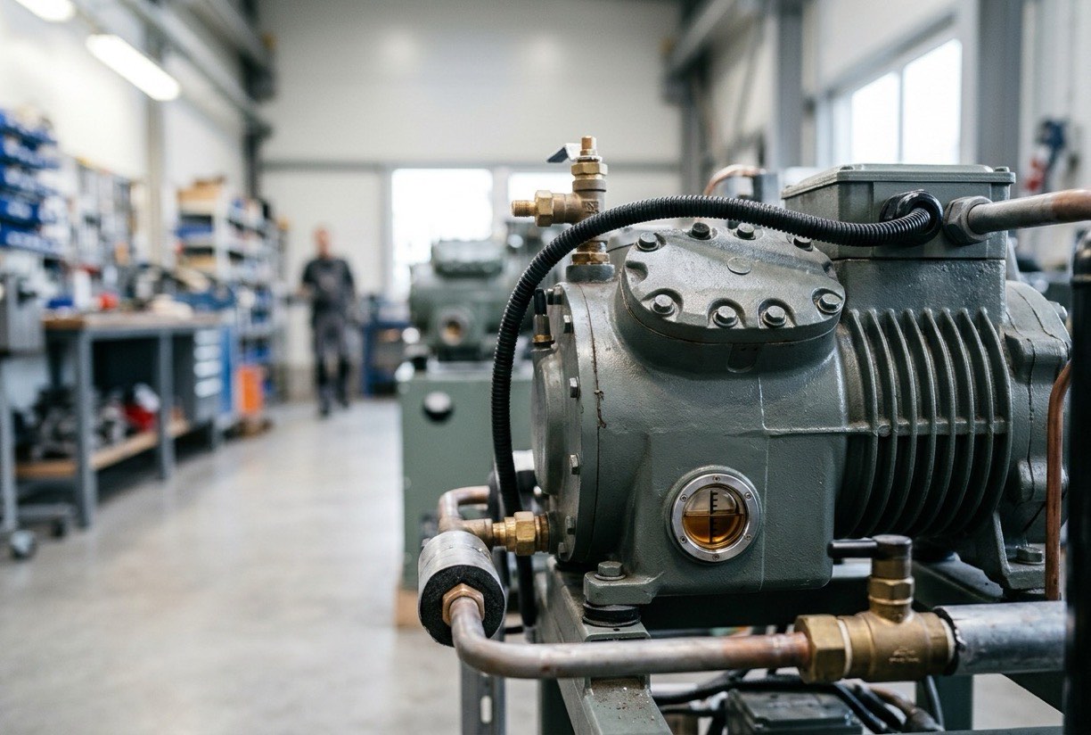
The oil in a refrigeration compressor lubricates the moving parts and helps remove heat. When the oil level falls, the compressor is under-lubricated, wears, and eventually fails. When the oil level is too high, oil can enter the circuit and reduce efficiency. This article explains why the oil level matters, how to read the sight glass, and the signs of a low oil level. Table Of Contents Why Does The Oil Level Matter? How Is The Sight Glass Read? What Are The Signs Of A Low Oil Level? How Is Oil Added? How Are Oil Leaks And Compatibility Checked? Frequently Asked Questions Why Does The Oil Level Matter? In the compressor, oil forms a film between the bearings, pistons, and other moving parts. This film reduces friction and limits wear. The oil also helps carry heat away from the windings and motor parts. Keeping the level correct is decisive for both the life and the efficiency of the compressor. Compressor oil reduces wear by forming a film between rubbing parts, carries heat away and keeps the seals supple. A correct oil level is needed for all of these functions to be performed together. When the oil is insufficient, the internal parts of the compressor lose this protection. When the oil level is low, the oil pump or the oil distribution passages can begin to draw in air. This causes fluctuations in oil pressure and disruptions to lubrication. Continuous under-lubrication can lead to rapid wear of the ball bearings and the pistons. An oil level that is too high also causes problems. Excess oil can foam inside the compressor and mix into the system, carried into the refrigeration circuit. In that case oil collects on the evaporator surface and heat transfer decreases. Oil is a fluid that continuously circulates in the refrigeration circuit. During this circulation some oil leaves the compressor, travels through the system and must return. If oil return cannot be achieved, oil loss in the compressor becomes visible, and this is often first noticed in the sight glass. The quality of the oil matters as much as its level. Dirty, humid or acidified oil can damage the compressor even when the level is correct. For this reason the level check should be made together with an assessment of the oil condition by eye and, where needed, by laboratory testing. The oil level is one of the basic indicators of how safely the compressor runs under load. The effect of a low or high level appears over the long term in the life of the compressor. The level check should therefore be part of the regular maintenance plan, not carried out only after a failure. How Is The Sight Glass Read? On many compressors the oil level is observed through a sight glass. The reading should be taken shortly after the compressor has stopped and the system has settled. The oil should be aligned with the mid-line of the glass. The colour and consistency of the oil should also be observed during the reading. Dark or dirty oil can indicate contamination in the system. The sight glass is a transparent window that allows the oil level of the compressor to be seen from outside. The reading should be taken when the compressor has stopped and the system has settled. In a running compressor, the oil may not show the correct level because of foam and agitation. For an accurate reading, the compressor should stand on a level floor. A reading taken in a tilted position can show a value different from the real level. The oil level should be judged by looking at which part of the mark in the middle of the glass the oil reaches. The colour and clarity of the oil should also be assessed separately in the sight glass. Oil that has darkened or become cloudy can be a sign of contamination or chemical breakdown. Colour alone does not give a definite decision, but it is a warning that calls for further checks. If there are traces of oil leakage around the glass, the source of the leak must be sought. The seal of the sight glass, looseness or cracking in its seat are common causes of leaks. A level check made while there is a leak can give misleading results over time. Reading the sight glass should be done under the same conditions at every check. The same temperature, the same stop time and the same position make the results comparable. This routine is the most reliable way of noticing slow changes in the level. The sight glass can show more than the level of the oil; it can also reveal changes in the condition of the system. Oil that bubbles, splashes or shows air bubbles in the glass can indicate moisture, a gas leak or a lubrication problem. Such observations should be evaluated together with the records. What Are The Signs Of A Low Oil Level? A low oil level can show up as increased noise, abnormal vibration, and a temperature rise. The compressor may also be stopped repeatedly by its protection circuit. When these signs appear, the compressor should not be run for long periods before the cause is identified. Noise: A knocking or ringing sound increases. Temperature: The compressor shell becomes hotter than expected. Protection: The oil pressure protection trips frequently. A low oil level usually shows itself first in sound and temperature. A change in the sound from the compressor, a shell that is hotter than expected, or protection devices tripping frequently are signs that should not be ignored. When these symptoms appear together, a level check should become the priority. The oil pressure protection stops the compressor when the oil pressure falls below the required level. If this protection trips often, it should be considered that the cause may not be oil shortage alone. The condition of the oil pump, any blockage of the oil passages and the filter should also be checked. Another result of inadequate lubrication is wear and scoring on the parts inside the compressor. This wear gradually spoils the sealing and reduces efficiency. If it is not noticed early, an oil shortage can turn into a motor or bearing failure. The cause of the symptoms is not always a shortage. Excess oil, foaming and an accumulation of oil in the system can produce similar symptoms. For this reason, reading the symptoms together with the level measurement prevents a wrong addition of oil. When symptoms caused by a low oil level appear, the compressor should be examined rather than run further. Continuing to run it can turn a small problem into a major repair. Early action reduces both the cost and the time. A fall in the oil level can affect not only the internal parts of the compressor but also the oil cooler and the oil filter. A disrupted oil circulation creates a risk of extra heating and blockage in these components. When symptoms appear, the whole oil circuit should therefore be reviewed. How Is Oil Added? Oil should be added using the oil type specified by the compressor manufacturer. Different oils may be incompatible and can cause problems in the system. Oil should be added with the system switched off and the compressor cooled, in a controlled quantity. After adding oil, the level should be checked again, and the compressor should be run briefly and measured again. Oil should be added only after it has been established that it is needed. Adding oil routinely without a real shortage can push the level too high. Before adding, the reason for the loss of oil should be investigated, and oil should not be added until the cause has been removed. The type of oil to be added must match the type specified by the compressor manufacturer. Mixing different oils can spoil the properties of the oil and reduce lubrication performance. The oil container should be clean and closed before the addition. The addition should be carried out in a way that prevents the system from becoming humid. Oil absorbs moisture as it is exposed to air, and this moisture can lead to acid formation and corrosion in the system. It is important to complete the addition quickly and not to leave the container open. After oil has been added, the compressor should be run for a while and the level checked again. This check confirms that the oil has spread through the system and that the correct level is visible in the sight glass. The results should be recorded. Adding oil is not a one-off task to be done and forgotten. Repeated additions show that oil loss is continuing in the system and indicate that the real cause must be found. For this reason the reason and the quantity of every addition should be recorded. The cleanliness of the tools used during addition is also important. A dirty pump, hose or funnel can carry foreign matter into the oil. For this reason the addition equipment should be checked before every use and kept clean. How Are Oil Leaks And Compatibility Checked? An oil leak is the first suspicion in systems that need oil frequently. Connections, gaskets, and body joints should be checked. When a leak is found, the leak should be repaired first and only then should oil be added. The oil type must also be compatible with the refrigerant used in the system. An incompatible oil can settle with the refrigerant and block the evaporator. Oil leaks can occur at connection points, in seals and at brazed seams. Leaked oil often combines with dust and dirt and leaves a visible trace. These traces give the first clues for finding the location of the leak. Oil compatibility should be assessed not only by its viscosity value but together with the refrigerant in use. Some oils can lose their properties when they mix with certain refrigerants. For this reason the choice of oil should be made together with the recommendations of the refrigerant and compressor manufacturers. Another factor affecting oil distribution in the system is the diameter and slope of the pipework. The return of oil to the compressor depends on the layout of the line. In a line where oil return is insufficient, oil accumulation and oil shortage can be seen together. When checking for leaks, attention should be paid to whether oil and refrigerant are leaking together. An oily leak can also be a sign of refrigerant loss. The leak should be found and repaired before the oil level check. Oil and leak tracking should be part of the maintenance records. If the connection, the time and the amount of oil loss are noted, recurring problems are easier to identify. These records are also an important source of data for decisions about oil changes. Repairing leak points affects not only the oil loss but also the pressure of the system. After repair the tightness and pressure test should be done again. The test result shows whether the leak has really been closed. Frequently Asked Questions Should the oil colour be checked? Yes. Dark, foaming, or badly smelling oil can indicate contamination, moisture, or combustion products in the system. In this case an oil change and cleaning of the system should be considered. Can any oil be used in any compressor? No. The oil type must match the standards specified by the compressor manufacturer and the refrigerant. The oil should not be changed without checking compatibility. What does frequent oil loss indicate? It usually indicates a leak, or a problem where oil is carried into the evaporator. The cause should be found rather than simply adding oil. How often should the oil level be checked? The frequency should be set according to the running time of the compressor, the load condition and the past problems of the system. In systems where oil loss has been seen or where protection trips often, checks should be more frequent. A regular record of checks helps to set a suitable interval. ? Can a compressor be run when the oil level is low? Running a compressor for a long time with a low oil level can cause rapid wear of its internal parts. If the oil pressure protection has tripped, restarting without finding the cause is not right. The reason for the fall in level should be examined first. ? What is the difference between an oil change and topping up the level? Topping up means adding a small quantity of oil to replace oil that has been lost. An oil change means draining the oil in the system and replacing it with new oil. A change is needed when the oil has become contaminated or broken down; topping up is done only to make up for a loss.
Read More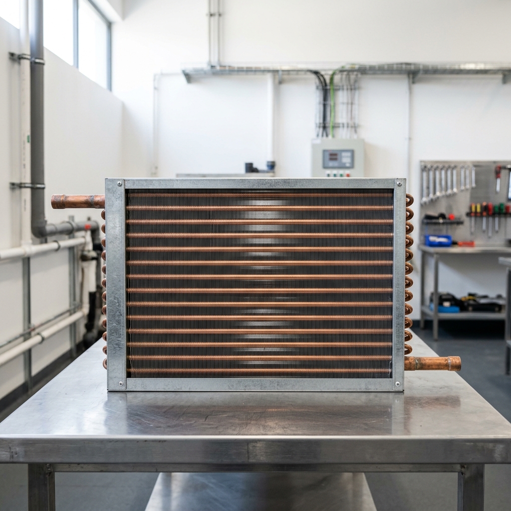
Evaporator manufacturing is the full set of interconnected production steps, extending from the preparation of tubes and fins to coil assembly, brazing, leak testing, and casing, fan and electrical connections. The capacity, durability and field reliability of an evaporator depend not only on the design but also on how carefully these steps are carried out. In this article, we go step by step through the stages an evaporator passes from the design desk to shipment and what is checked at each stage. Table of Contents Which Design Step Does Evaporator Manufacturing Start With? How Are Fins Pressed And How Are Tubes Prepared? Why Is The Tube Expansion Process Important? How Are The Header, Distributor And Brazing Done? How Are Leak And Pressure Tests Applied? What Should Be Considered When Choosing A Quality Evaporator Manufacturer? Frequently Asked Questions Which Design Step Does Evaporator Manufacturing Start With? Evaporator manufacturing starts with the thermal design step, in which the coil geometry and circuit arrangement are calculated based on data such as the required capacity, room temperature, refrigerant and air flow rate. At this stage, tube diameter, fin spacing, number of rows and number of circuits are determined. After the thermal calculation, mechanical design is carried out: casing dimensions, fan layout, drain pan, the position of defrost heaters and installation details are drawn. The design output is converted into technical documentation containing the cutting lists, bending dimensions and brazing points to be used at each step of production. Since an error made at this step carries over into all subsequent stages, design verification is the critical first link of production. How Are Fins Pressed And How Are Tubes Prepared? Fins are produced by pressing coil strip sheets of aluminium, or a different material depending on project requirements, with special dies to punch holes, form collars and cut them to the required length. The profile on the fin surface and the collar height determine both heat transfer and the spacing between fins. At the same time, tubes made of copper or another material selected according to project requirements are straightened, cut to size and bent into a hairpin (U) shape. During bending, it is important that the tube is not crushed and that its wall thickness is preserved; otherwise, pressure drop and strength problems may arise on the refrigerant side. The prepared fins are stacked and the bent tubes are passed through the holes of this stack to form the coil body. Why Is The Tube Expansion Process Important? The tube expansion process is important because it provides tight mechanical contact between the tubes and the fin collars, enabling heat to be transferred efficiently from the refrigerant to the fin. If the contact remains weak, the air gap in between creates thermal resistance and the coil cannot reach the calculated capacity. Expansion is generally carried out by passing a mechanical mandrel through the inside of the tubes; in some applications, hydraulic methods may also be used. The expansion ratio is adjusted according to the tube material, wall thickness and fin collar size. Excessive expansion leads to thinning of the tube, while insufficient expansion leads to loss of contact. For this reason, mandrel dimensions and process parameters are checked regularly. How Are The Header, Distributor And Brazing Done? The header, distributor and return bend connections are brazed with suitable filler material and controlled heating, turning the coil circuits into a single refrigerant system. Brazing quality directly affects the tightness and long-term reliability of the evaporator. Return bends are fitted to the open ends of the expanded tubes and brazed; then the distributor and capillary tubes are connected to the inlet side, and the suction header to the outlet side. Applying shielding gas during brazing to prevent oxide formation inside the tube is a common method. Keeping the capillary tubes at equal lengths is important for distributing the refrigerant evenly to all circuits. After brazing, the joints are visually inspected and cleaned. How Are Leak And Pressure Tests Applied? Leak and pressure tests are applied by loading the coil with a test pressure appropriate to its design pressure and then checking all connections with leak detection methods. The test pressure and method are determined specifically for the project according to the refrigerant type and the relevant requirements. The pressure test aims to reveal the mechanical strength of the coil, and the leak test aims to reveal micro-level leaks. For leak testing, underwater bubble checks, tracer gas detection or vacuum methods may be used. Coils that pass the test are dried, charged with protective gas to prevent moisture ingress and sealed. Then the casing, fans, drain pan, defrost heaters and electrical connections are mounted; after the final functional check, the product is packaged and prepared for shipment. What Should Be Considered When Choosing A Quality Evaporator Manufacturer? When choosing a quality manufacturer, it is necessary to look not only at the product catalogue but also at how the design and production processes are managed. The following items can guide the evaluation. Ability to provide project-specific thermal calculations and technical documentation Defined quality control processes in the expansion, brazing and testing steps Ability to offer material and coating options according to the application and environment Commissioning, spare parts and after-sales technical support If you would like information about our production processes or an evaporator suitable for your project, you can talk to the Günay Soğutma team. Frequently Asked Questions How long does it take to manufacture an evaporator? The time varies depending on whether the product is standard or project-specific, the quantity and material availability, and is clarified at the order stage. Can another material be used instead of copper tube? Different tube materials may be preferred depending on the refrigerant type and environmental conditions; the selection is made according to the application. At which stage of production is the fin coating applied? It depends on the type of coating; pre-coated fin material can be used, or coating can be applied to the entire coil after assembly. Does every evaporator go through a pressure test? Leak and pressure testing is one of the basic quality steps expected to be applied to every coil in series production. Can evaporators be manufactured in custom dimensions? Yes, design and production in project-specific dimensions can be carried out according to space or capacity requirements. How is the evaporator protected during shipment? The coil is charged with protective gas and sealed, and the fin surfaces and connections are protected against impact with suitable packaging. How can I get an evaporator quotation for my project? You can request a quotation suitable for your project by sharing your capacity, room temperature, refrigerant and layout information with the Günay Soğutma team.
Read More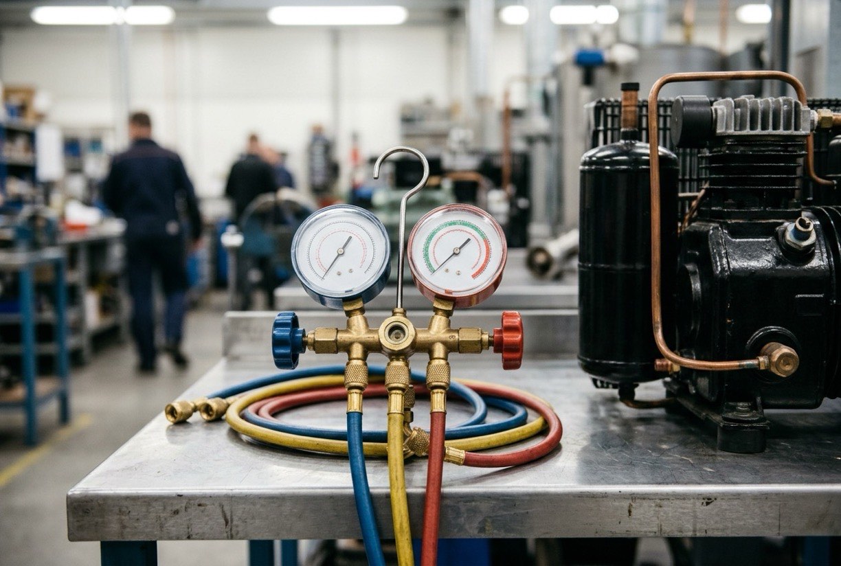
Pressure measurements are the quickest way to understand the current state of a refrigeration circuit. Suction and condensing pressures can be misleading when read alone, but when they are read together with temperatures they give a clear picture of the evaporator, the condenser, and the compressor. This article explains what the pressure values mean, how they relate to superheat and subcool, and the causes of common deviations. Table Of Contents What Does The Suction Pressure Mean? What Does The Condensing Pressure Show? How Are Superheat And Subcool Read? Which Common Deviations Have Which Causes? How Is The Measurement Made Safely? Frequently Asked Questions What Does The Suction Pressure Mean? The suction pressure is the pressure of the gas leaving the evaporator outlet towards the compressor. This value indicates how much cooling the evaporator is doing. A falling suction pressure can indicate insufficient evaporation in the evaporator, while a rising one can indicate that the evaporator is taking a heavier load. The suction pressure should be interpreted by comparing it with the pressure-temperature table of the refrigerant in use. Suction pressure is the pressure on the compressor's suction side, along the line from the evaporator outlet to the compressor inlet. This value is the first indicator of how much refrigerant the evaporator is evaporating and under which conditions the compressor is working. Even read on its own, it gives a picture of the general state of the system. When suction pressure falls, it is often assumed that there is not enough heat exchange in the evaporator or that the refrigerant quantity has decreased. This can come from a dirty evaporator, a low refrigerant charge or a restricted line. A low pressure does not always have a single cause, so the value should be read together with other measurements. A rising suction pressure is also a warning sign. Excess heat exchange in the evaporator, too much refrigerant, or a fall in compressor efficiency can pull this value up. A rising suction pressure can increase the risk of liquid slugging and should therefore be watched closely. Suction pressure fluctuates by itself as the ambient temperature and the load change. A single instantaneous reading may therefore not reflect the real state of the system. Readings taken under stable operating conditions and repeated a few times give a more reliable picture. The relationship between suction pressure and evaporator temperature is one of the most practical ways to monitor stability. When this relationship changes, the other values must be checked to find the reason. A change in one value does not necessarily change the whole picture. What Does The Condensing Pressure Show? The condensing pressure is the pressure of the gas leaving the compressor discharge towards the condenser. It shows whether the condenser can reject heat to the outside. A high condensing pressure can indicate that the condenser is receiving insufficient air, is dirty, or that the outdoor temperature is high. If the condensing pressure becomes too low, enough pressure difference may not develop across the expansion valve, and the evaporator may not be fed properly. Condensing pressure is the pressure on the discharge side of the compressor, at which the refrigerant condenses in the condenser. The ability of the condenser to reject heat shows in this value. The outside air temperature, the operation of the condenser fans and the cleanliness of the condenser surface all affect this pressure directly. If the condensing pressure runs high, the condenser is struggling to reject heat. This can come from a dirty condenser surface, a fan that is not running, excess refrigerant or poor ventilation. High pressure stresses the compressor motor and can cause protective devices to trip. A low condensing pressure is not always a good sign either. It can mean over-cooling in the condenser or insufficient pressure at the compressor discharge. In that case a conclusion should be drawn together with the suction pressure and the liquid-side values. The condensing pressure varies during the day with the outside air temperature. For this reason the outside condition at the moment of measurement should be noted. Comparing the same system at different temperatures can lead to misleading conclusions. Control of the condensing pressure depends not only on the fans but also on where the condenser is placed. If warm air accumulates around the condenser, the condensing pressure comes out higher than expected. The layout should allow the air to circulate freely. How Are Superheat And Subcool Read? Pressures are not interpreted alone; the saturation temperature corresponding to the pressure is compared with the actual temperature. At the evaporator outlet this difference is called superheat, and at the condenser outlet it is called subcool. Superheat: The difference between the evaporator outlet temperature and the saturation temperature of the suction pressure. It shows liquid slugging risk and how well the evaporator is used. Subcool: How far the liquid leaving the condenser is below its saturation temperature. It shows whether the liquid line has adequate cooling. Superheat and subcool are two basic values used to read the suction and liquid sides together. These values should be interpreted together rather than alone, to understand whether the system is working in balance. Knowing which value points to which fault is the basis of setting up the control logic correctly. A low superheat indicates a risk of liquid returning to the evaporator. Such a condition creates a risk of liquid slugging at the compressor and can cause serious damage over the long term. A high superheat, on the other hand, indicates that part of the evaporator is not working effectively. A low subcool suggests a tendency for the liquid line to flash and for gas bubbles to form in the system. This needs control of the expansion valve and the liquid line. The subcool value also gives information about the balance of the condenser and the refrigerant quantity. Superheat and subcool measurements should be taken during a steady and stable operating cycle. Values taken when the compressor has just started or when the outside conditions are changing rapidly reflect temporary states. The measurement should therefore be planned for a moment when the system has settled. Reading superheat and subcool together also shows whether the setting of the expansion valve is correct. The valve tries to establish a balance between these two values. The moment when the setting needs to change is recognised when that balance is lost. Which Common Deviations Have Which Causes? When pressure and temperature values are read together, deviations point to specific causes. Low suction pressure with high superheat is usually linked to insufficient refrigerant, a blocked filter, or a restricted valve. High condensing pressure can be linked to a dirty condenser, an airflow obstruction, or an excess of refrigerant charge. It is the combined change of the values, rather than any single value, that is decisive for diagnosis. Interpreting deviations depends on looking at several values together, not at a single one. A low suction pressure with a high condensing pressure, for example, can point to different causes when taken separately. Deviations should therefore be assessed through a recorded table of measurements. A dirty condenser raises the condensing pressure, which both increases energy consumption and strains the compressor. Cleaning and fan checks can largely prevent this problem. When the condensing pressure rises, the condition of the condenser should be checked first. A dirty evaporator or a restricted suction line lowers the suction pressure and causes a loss of capacity. In such a case the evaporator surface, the filter and the line diameter should be reviewed together. If the pressure drop is seen together with frequent defrosting or a fall in airflow, the cause is easier to find. Too much or too little refrigerant affects both suction and condensing pressures. With too little refrigerant the superheat rises while the subcool falls; with too much, the reverse is seen. This relationship shows why charge control must be done together with superheat and subcool. Some deviations are temporary. Values seen after a door opening or after a defrost may not reflect the true state of the system. Such values should be compared with a stable operating cycle, and temporary deviations should be distinguished from lasting faults. How Is The Measurement Made Safely? Measurements should be taken when the system runs steadily and the load condition is known. The manifold and hoses must be connected to the correct points, and the connections should be checked for leaks. Protective equipment should be used because of high pressures and hot surfaces. Measurement records should be kept with the date and the system load, and used for later comparison. The Günay Soğutma technical team can support the evaluation of measurement results. Pressure measurement involves contact with the compressor and the lines. A wrong connection or unauthorised intervention can lead to refrigerant escaping and to injury. Before measuring, the state of the system, the safety of the equipment and the suitability of the connection points should be checked. Calibration of the measuring instruments is a basic condition for the reliability of the values. A gauge or sensor with uncertain calibration can lead to a wrong diagnosis. A routine where the instruments are checked regularly and their records are kept should be set up. Opening and closing the lines during measurement requires the refrigerant to be handled in a controlled way. Fast and careless intervention increases both the safety risk and the risk of air or moisture entering the system. Every step should be carried out in order and according to a defined procedure. Recording the measurement results is also part of safe operation. The date, the time, the outside conditions and the name of the person taking the measurement are valuable for later comparisons. When records are kept regularly, the moment when a deviation started can also be seen more clearly. The training of the person taking the measurement is also decisive for safety and accuracy. A measurement made by someone without knowledge of pressure and refrigerant can create a risk both for that person and for the system. Measurement should therefore be carried out by an authorised and trained technical person. Frequently Asked Questions When should measurements be taken? They should be taken after the system has run steadily, in a period when the load is not changing. A record should always be kept after the first start-up and after maintenance. Are pressure values alone enough? No. Pressures should be evaluated together with temperatures. Diagnosis without values such as superheat and subcool can be misleading. What should be considered during measurement? The correct refrigerant pressure-temperature table should be used, the connections should be checked for tightness, and protective equipment should be worn against the risk of high pressure. Which instruments are needed for measurement? Pressure measurement needs a calibrated gauge set, a reliable temperature sensor and suitable connection hoses. Digital instruments can also be used for recording values. The measuring range of the instruments should be chosen to cover the working pressure of the system. How can a leak in the system be recognised? A low suction pressure together with a high superheat and a low subcool may be a sign of a refrigerant shortage. However, this alone is not conclusive proof. A suspected leak should be confirmed through a visual check and a suitable leak detection method. How are compressor discharge temperature readings used together with pressure values? When the discharge temperature is read together with the pressure values, the thermal state of the system is better understood. A very high discharge temperature may point to insufficient cooling or a problem with oil circulation. These readings should be used together to monitor the health of the system.
Read More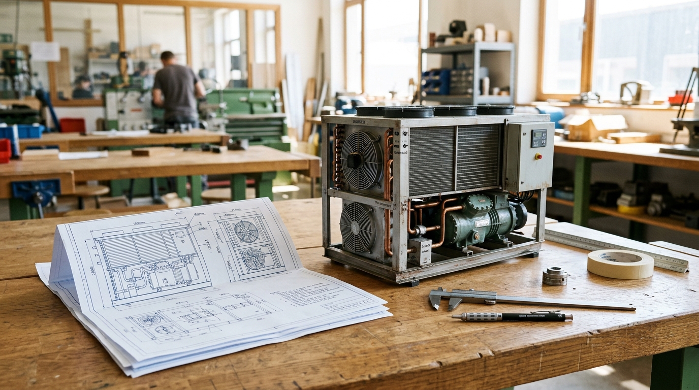
Total cost in refrigeration equipment is the sum of the costs arising over the service life of a unit, covering not only its purchase price but also installation, energy, maintenance, breakdown, spare parts and end-of-life expenses. Investment decisions are often made based solely on the initial price; yet the operating expenses paid over the years can easily exceed this price. In this article, we discuss the components of total cost, the share of energy and maintenance, the long-term effect of quality choices and how you can compare quotations more fairly. Table of Contents What Does Total Cost Of Ownership Mean? Which Items Are Included In The Initial Investment Cost? How Does Energy Consumption Affect Total Cost? How Are Maintenance, Breakdown And Downtime Costs Taken Into Account? How Do Equipment Life And Material Quality Reflect On Cost? What Should Be Considered When Comparing Quotations By Total Cost? Frequently Asked Questions What Does Total Cost Of Ownership Mean? Total cost of ownership refers to the sum of all direct and indirect expenses that a refrigeration unit imposes on the business over the period from its purchase to its decommissioning. This approach makes it possible to compare options with different prices and features on the same basis. The calculation generally covers initial investment, energy, planned maintenance, unexpected breakdowns, product loss and end-of-life expenses. Discounting future expenses to present value provides a more realistic picture for long-term investments. Since the period of use, energy price and interest assumptions vary from business to business, the results are also project-specific; the same unit can produce a different total cost in two different facilities. Which Items Are Included In The Initial Investment Cost? In addition to the unit price, the initial investment cost includes transportation, installation, piping and electrical work, supporting structure, control system and commissioning expenses. Focusing only on the unit price can overlook the fact that these items are handled differently across quotations. For example, a lighter unit can reduce the need for additional structure on the roof; an integrated control panel can lower on-site wiring labour. On the other hand, accessories excluded from the quotation, crane hire or additional insulation work can strain the budget later. For this reason, when comparing initial investment, the scope of the quotations should be examined line by line and missing items should be clarified. How Does Energy Consumption Affect Total Cost? In continuously operating refrigeration systems, energy consumption generally constitutes the largest operating item of total cost, and small efficiency differences can turn into significant amounts over the years. The compressor, fans, defrost heaters and auxiliary equipment are the main sources of this consumption. An evaporator or condenser with a larger surface can reduce the temperature difference, allowing the compressor to operate at a lower pressure ratio. Control methods such as variable-speed fans and demand defrost also provide savings under partial load conditions. However, the additional cost of these choices should be evaluated together with the facility's operating hours and energy prices; the payback period should be calculated separately for each project. How Are Maintenance, Breakdown And Downtime Costs Taken Into Account? Maintenance, breakdown and downtime costs are taken into account by estimating planned maintenance labour, spare parts, emergency service expenses and the product or production loss incurred while refrigeration is down. These items are often invisible at the quotation stage, but they occupy an important place in the business's budget. Units with easy maintenance access, that work with standard spare parts and that have a cleanable coil structure reduce labour time. In applications such as food, pharmaceuticals or data centres, the cost of a single downtime can approach the price of the unit; in this case, redundant design or monitoring systems become economically meaningful. The facility's risk tolerance determines how much weight is given to these items. How Do Equipment Life And Material Quality Reflect On Cost? Equipment life and material quality reflect on total cost by determining over how many years the investment will be spread and to what extent performance will be maintained during this period. A unit with a shorter life may lose its initial price advantage due to the need for early replacement. Failure to select a suitable coil material or coating in corrosive environments can lead to early deterioration and capacity loss in fins and tubes. As capacity drops, energy consumption increases and breakdowns become more frequent. On the other hand, choosing the most durable material for every environment can also create unnecessary cost. The right approach is to determine the material and coating choice according to the operating environment and the expected period of use. What Should Be Considered When Comparing Quotations By Total Cost? To compare quotations fairly, all options must be evaluated on the basis of the same assumptions and the same scope. The following items make this evaluation easier. Capacity and energy consumption values given under the same design conditions Installation, control and accessory items included and not included in the quotation scope Maintenance access, spare parts availability and service support Material selection suitable for the operating environment and expected service life If you would like a total cost-focused assessment for your project, you can contact the Günay Soğutma team. Frequently Asked Questions Does a cheap unit always end up costing more? Not always; in projects with low operating hours or short duration, the initial price can be decisive. The result depends on the conditions of use. What data is needed for a total cost calculation? Annual operating hours, energy price, planned period of use, maintenance plan and the performance values in the quotations are the basic data. How is the payback period of energy-efficient equipment calculated? A simple payback period can be found by dividing the additional investment amount by the annual energy savings; in a more detailed analysis, the time value of money is also taken into account. Does a maintenance contract reduce total cost? Regular maintenance can reduce performance loss and unexpected breakdowns. The benefit of the contract should be evaluated according to the criticality level of the facility. Is it more economical to refurbish the existing system or replace it completely? This decision depends on the condition of the existing equipment, refrigerant compatibility and the energy difference; it is recommended to calculate both scenarios separately. What do end-of-life expenses cover? Dismantling, refrigerant recovery, transportation and recycling operations are among end-of-life expenses. How can I have a total cost analysis done for my own project? You can request a project-specific assessment by sharing your capacity, operating time and existing quotations with the Günay Soğutma team.
Read More
Fill out the form to discover the most suitable high-end products for your projects. Contact Us Now.
Fairs
Strong Connections Through Fair Participation
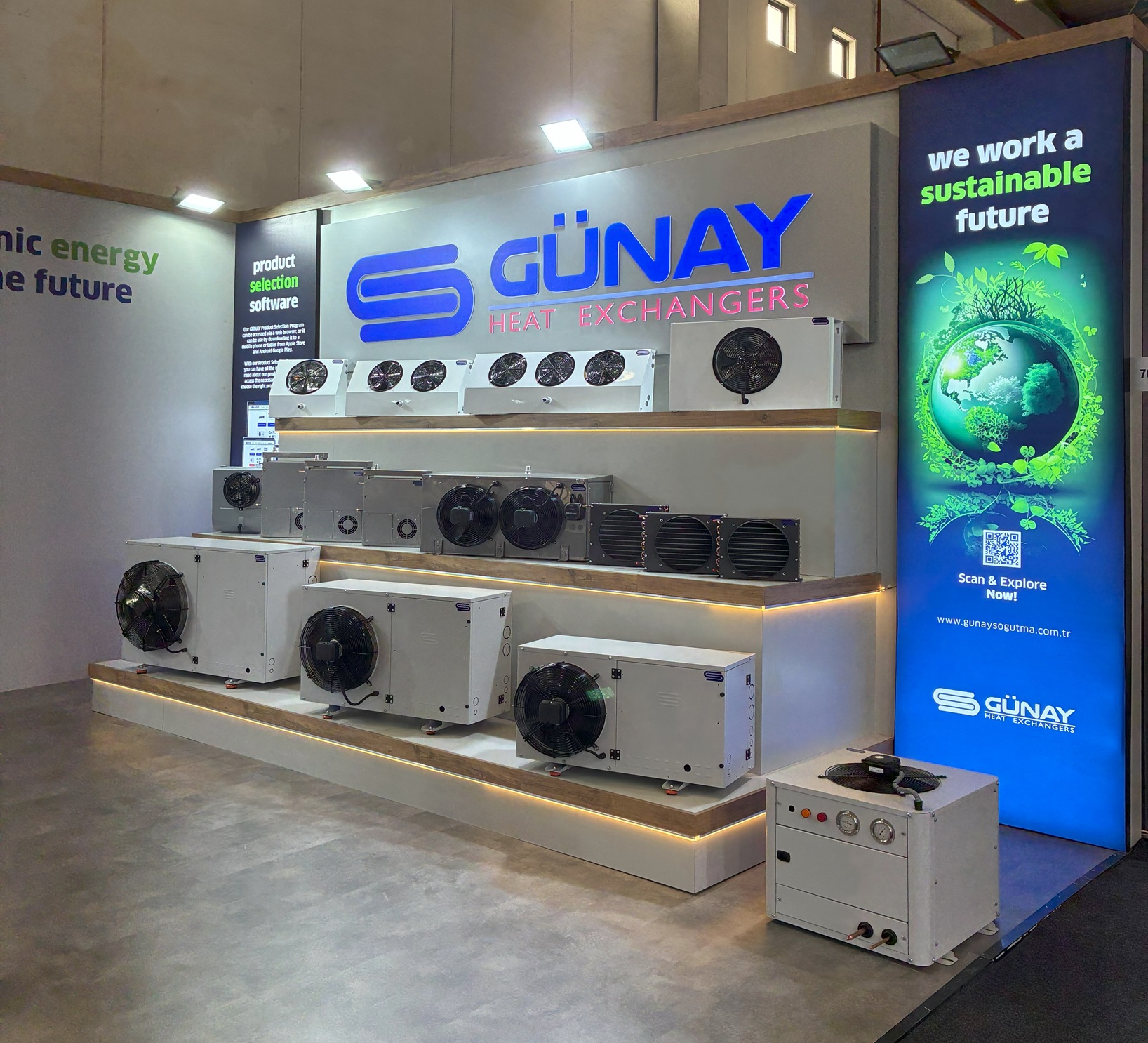
Hostech 2025
This year, Hostech by TUSİD 2025 was held on May 27–31 at the Istanbul TÜYAP Fair and Congress Center. As Turkey’s largest and Europe’s second largest HORECA fair, it welcomed approximately 35,000 visitors from 140 countries across a 45,000 m⊃2; exhibition area. Günay Soğutma proudly took part in this major event. At our booth, we showcased our innovative industrial cooling products and sustainable solutions, while also connecting with professionals from both Turkey and abroad. For us, Hostech was more than just a fair; it was a valuable opportunity to build new business partnerships, strengthen existing relationships, and represent our company more powerfully in the international market. The strong interest from foreign buyer delegations once again proved that we are on the right track. We sincerely thank all our visitors and look forward to meeting again at upcoming fairs.
Read More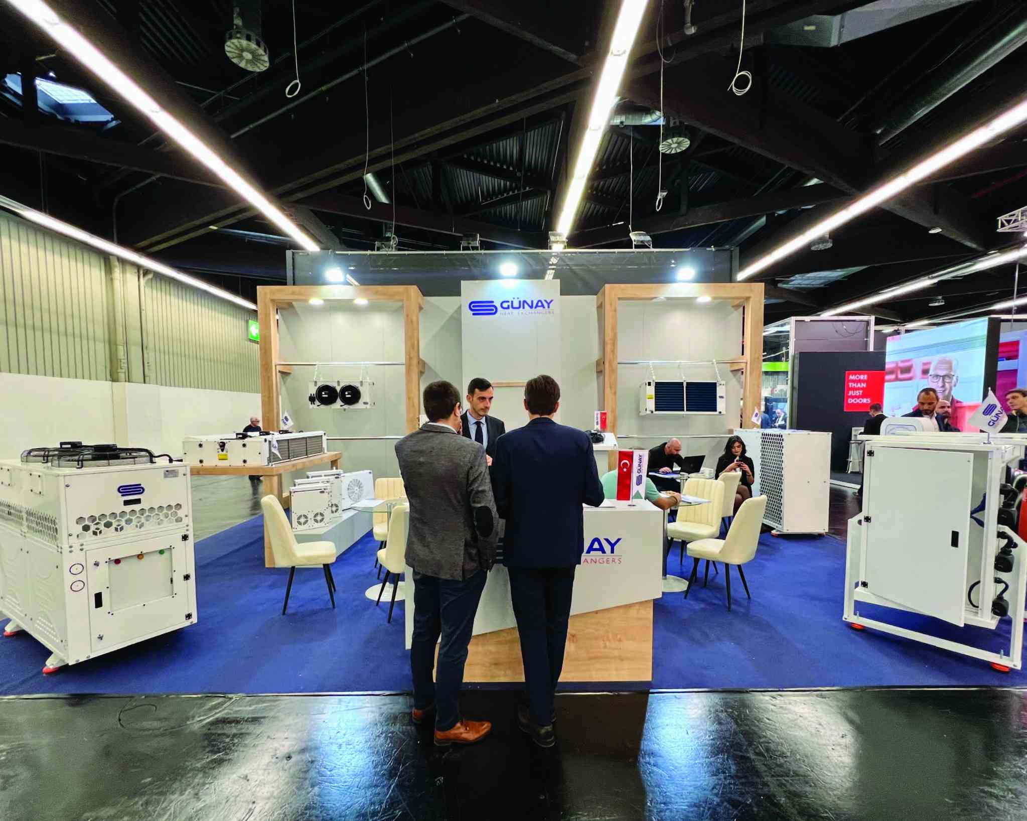
Chillventa 2022
Thank You to Everyone Who Joined Us at Chillventa 2022! We would like to extend our heartfelt thanks to all participants and valued customers who visited our stand at Chillventa 2022. Your interest and the time you shared with us were a tremendous source of motivation, allowing us to present our innovative cooling solutions and share our vision within the industry. The connections we have built with you strengthen our leadership goals and inspire us to provide more efficient and sustainable solutions in the future. We look forward to building new projects and strong partnerships together!
Read More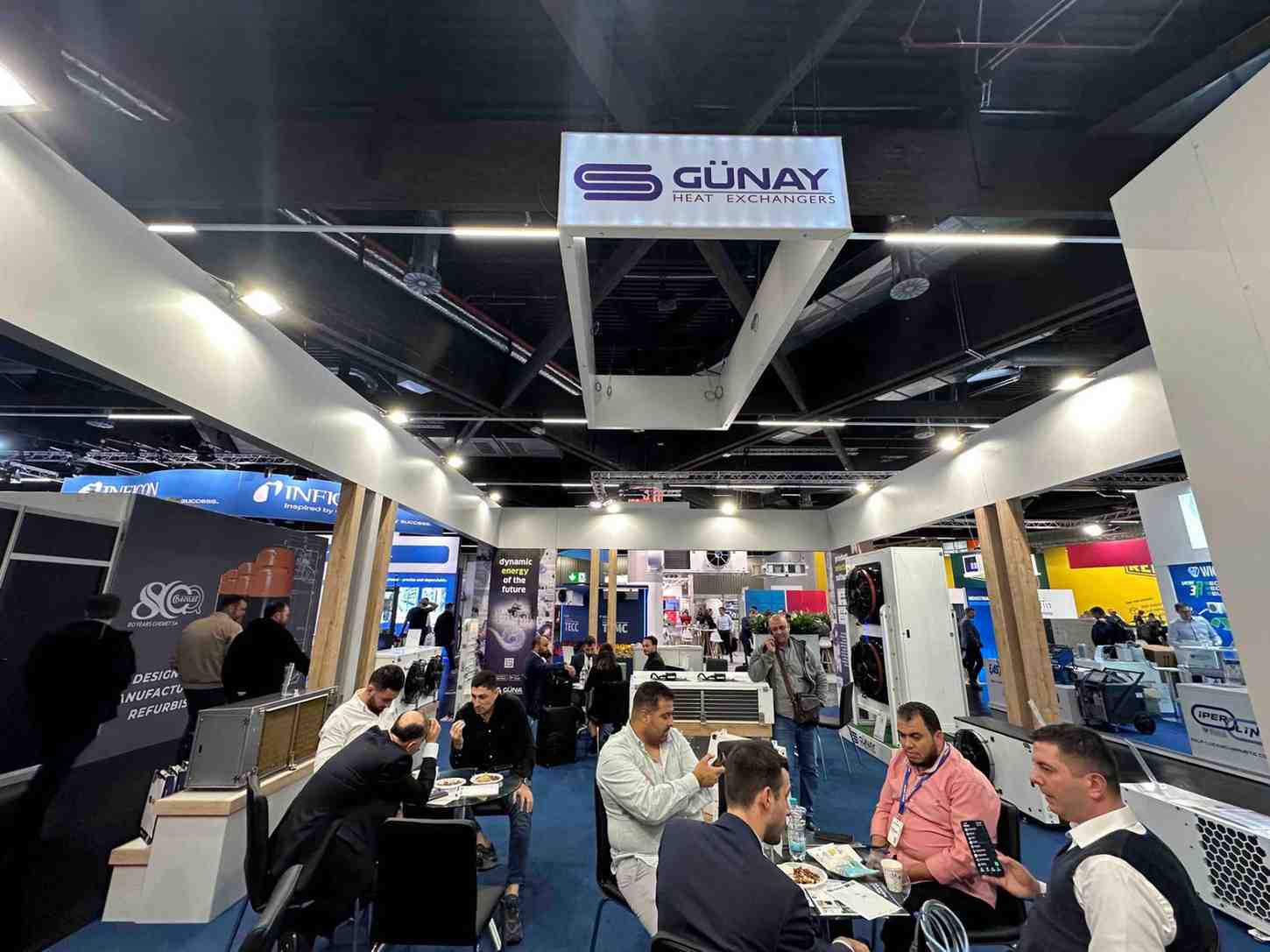
Chillventa 2024
Günay Soğutma participated in the Chillventa 2024 Fair, seizing the opportunity to showcase the latest innovations in the sector. During the event, we shared our newest technologies and solutions in the field of cooling and air conditioning with attendees. The fair served as an important platform to connect with industry professionals and foster new collaborations. Visitors had the chance to explore our innovative products and sustainable solutions while gaining insight into our customer-oriented approach. Chillventa 2024 provided not only an opportunity for knowledge exchange but also a chance to keep up with the latest industry trends. We are pleased to have established new business connections and strengthened existing relationships through this experience. We would like to extend our gratitude to all the visitors who joined us at the fair. We eagerly look forward to meeting you again at future events!
Read More
HVAC-R Egypt Expo 2024
With the solutions we presented at HVAC-R EGYPT EXPO, we reinforced our reliability and sustainability principles in the refrigeration and heat transfer sector in Egypt.
Read More
HVAC-R London 2023
HVAC Refrigeration Live, as an important event in the industry, offered a very valuable experience for us. We would like to express our sincere thanks to all exhibitors and customers who visited our booth for their interest and time. The strong ties we have established with you give us great motivation to maintain our leadership in the industry and to carry our solution-oriented approach even further.
Read More
ISK-SODEX Istanbul 2023
We participated in ISK-SODEX 2023, one of the leading exhibitions of the air conditioning industry. We would like to thank all our customers and exhibitors who showed great interest in our stand.
Read More
AquaTherm Exhibition 2023
Thank you to all our customers and exhibitors who visited our booth at AquaTherm Exhibition 2023. Your intense interest made us very happy and we were proud to share our innovations in the sector.
Read More
C&R Madrid 2023
The C&R Madrid 2023 fair was an unforgettable experience for us as an important event in the industry. We extend our heartfelt thanks to all participants and customers who visited our stand for their interest and time. The connections we established with you inspire us to continue our leadership in the industry and strengthen our solution-oriented approach. We look forward to building a more efficient and sustainable future togethe
Read More Gallery
Strong And Reliable Since 1986


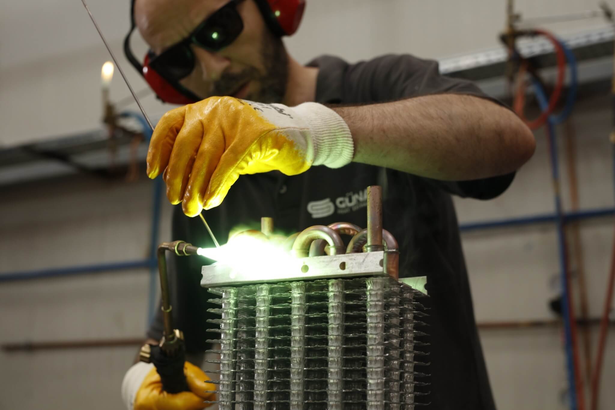

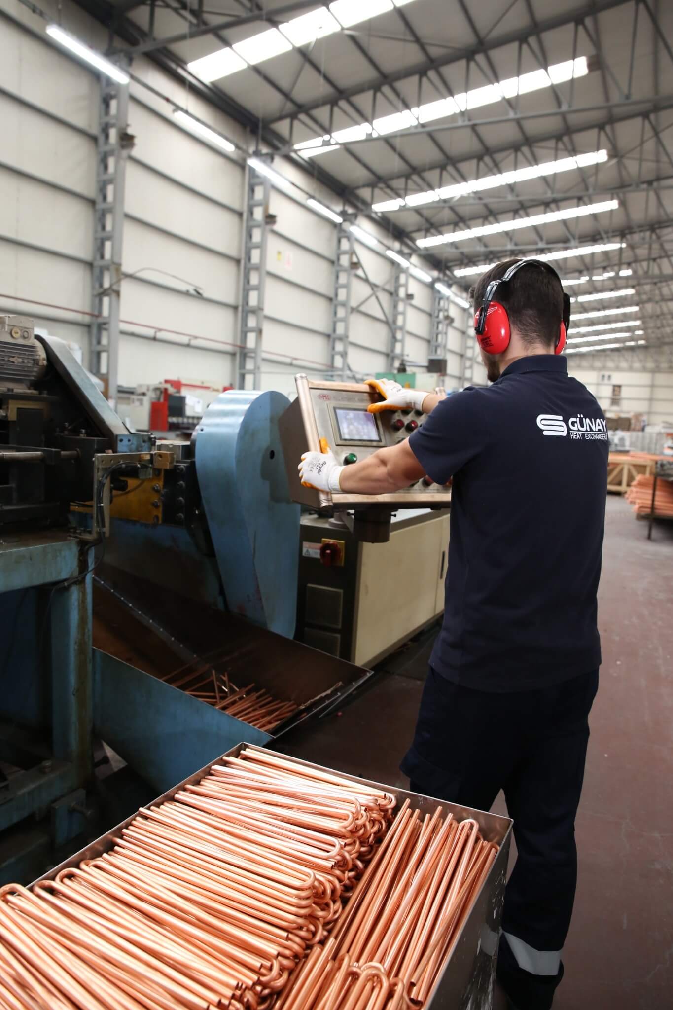

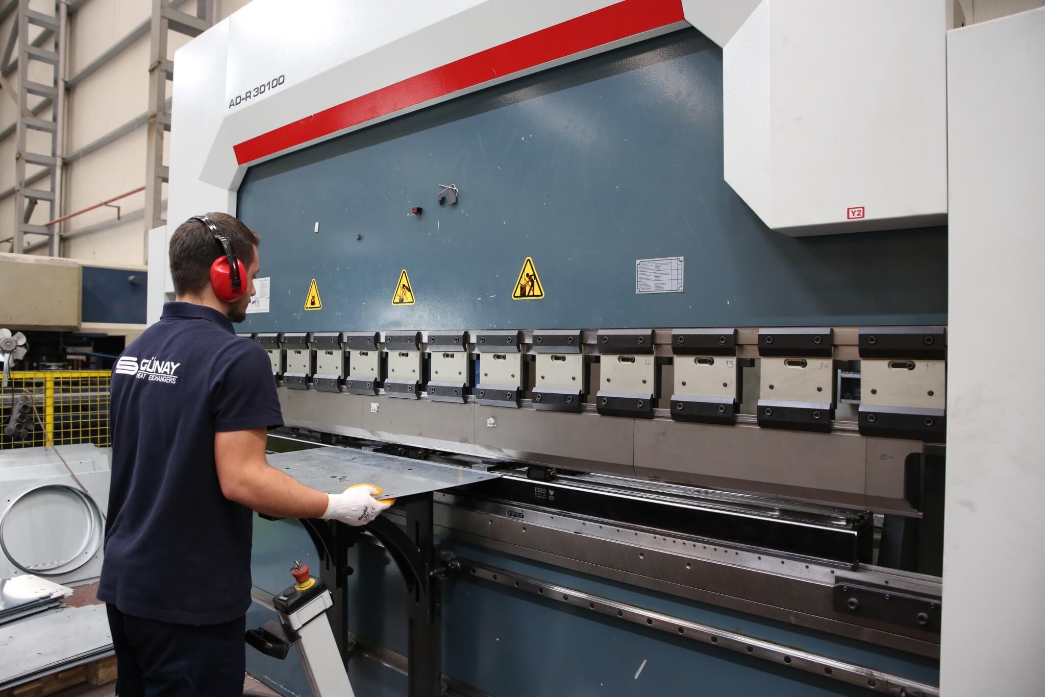
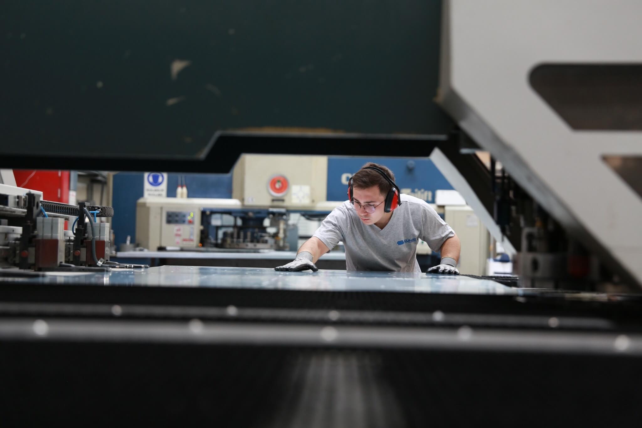
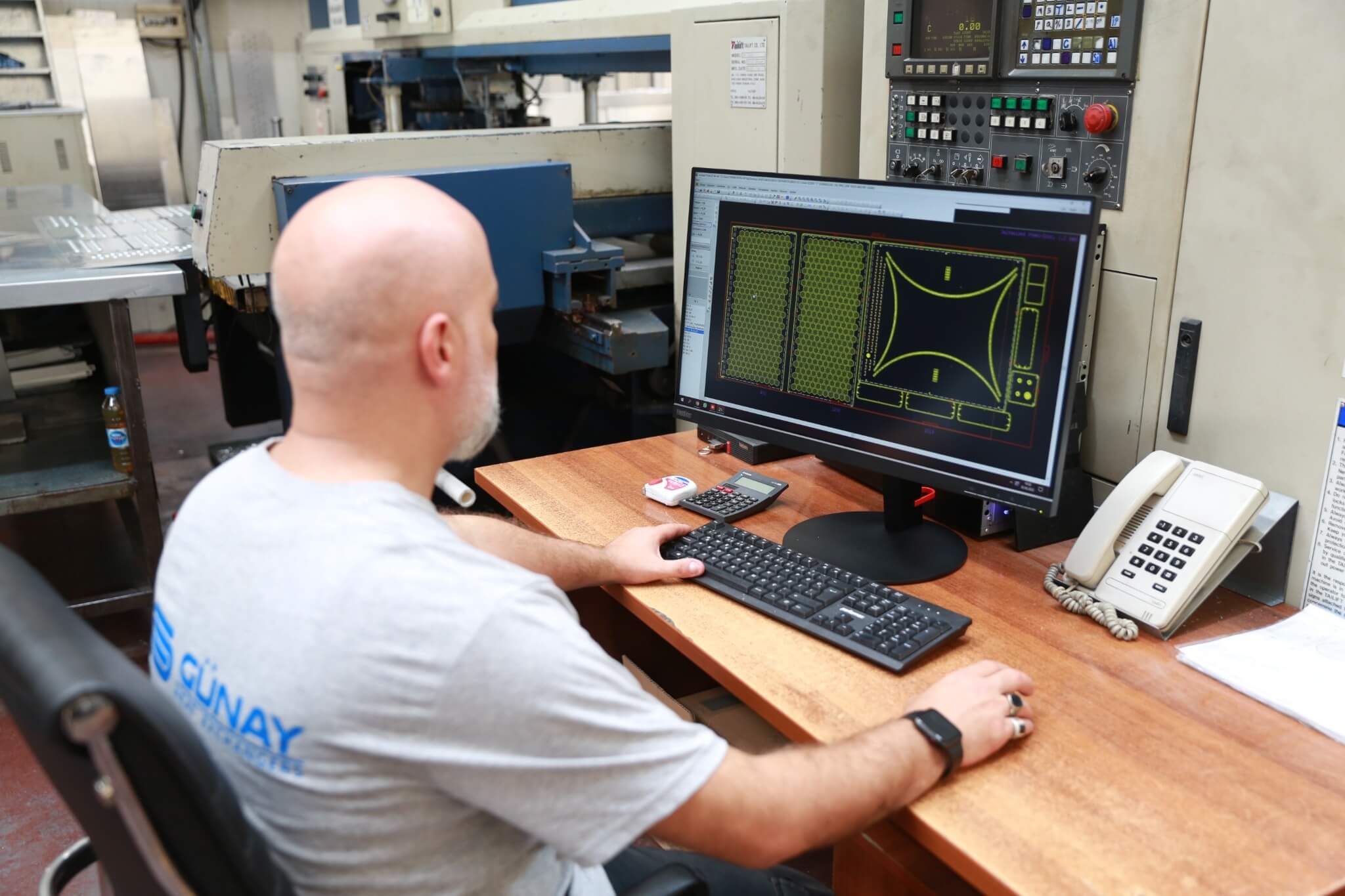
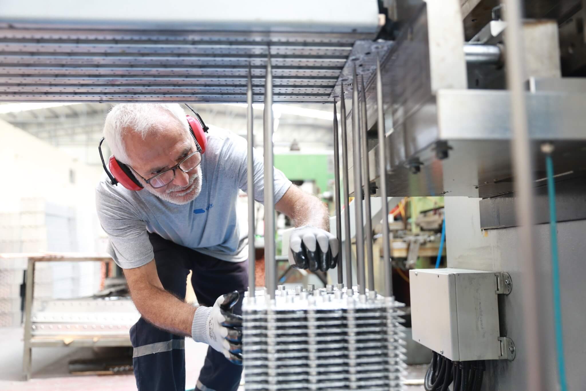
dynamic energy of the future
